H-Bridge
An H-bridge is a transistor-based circuit capable of driving motors both clockwise and counter-clockwise. It’s an incredibly popular circuit – the driving force behind countless robots that must be able to move both forward andbackward.
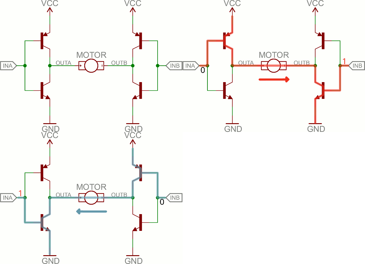
Fundamentally, an H-bridge is a combination of four transistors with two inputs lines and two outputs:
(Note: there’s usually quite a bit more to a well-designed H-bridge including flyback diodes, base resistors and Schmidt triggers.)
If both inputs are the same voltage, the outputs to the motor will be the same voltage, and the motor won’t be able to spin. But if the two inputs are opposite, the motor will spin in one direction or the other.
The H-bridge has a truth table that looks a little like this:
| Input A | Input B | Output A | Output B | Motor Direction |
|---|---|---|---|---|
| 0 | 0 | 1 | 1 | Stopped (braking) |
| 0 | 1 | 1 | 0 | Clockwise |
| 1 | 0 | 0 | 1 | Counter-clockwise |
| 1 | 1 | 0 | 0 | Stopped (braking) |
Reference
| Reference | URL |
|---|---|
| Spark Fun Transistos | https://learn.sparkfun.com/tutorials/transistors |
