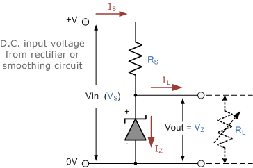
Cheap Voltage Regulator using Zener Diodes
A zener diode is always operated in its reverse biased condition. A voltage regulator circuit can be designed using a zener diode to maintain a constant DC output voltage across the load in spite of variations in the input voltage or changes in the load current. The zener voltage regulator consists of a current limiting resistor RS connected in series with the input voltage VS with the zener diode connected in parallel with the load RL in this reverse biased condition. The stabilized output voltage is always selected to be the same as the breakdown voltage VZ of the diode.
Full Wave Bridge Rectifier
This type of single phase rectifier uses four individual rectifying diodes connected in a closed loop “bridge” configuration to produce the desired output.
The main advantage of this bridge circuit is that it does not require a special centre tapped transformer, thereby reducing its size and cost. The single secondary winding is connected to one side of the diode bridge network and the load to the other side as shown below.
References
| Reference | URL |
|---|---|
| Zener Diode as Voltage Regulator | https://www.electronics-tutorials.ws/diode/diode_7.html |
| Full Wave Rectifier | https://www.electronics-tutorials.ws/diode/diode_6.html |

