Layered Architecture Pattern
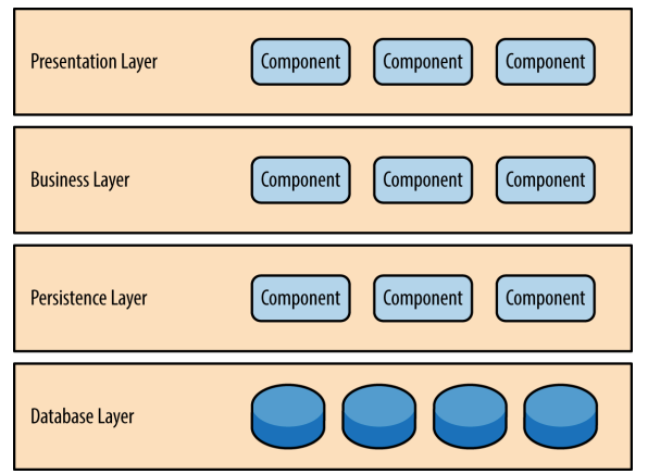
Components within the layered architecture pattern are organized into horizontal layers, each layer performing a specific role within the application (e.g., presentation logic or business logic). Although the layered architecture pattern does not specify the number and types of layers that must exist in the pattern, most layered architec‐ tures consist of four standard layers: presentation, business, persistence, and database.
A request originating from the presentation layer must first go through the business layer and then to the persistence layer before finally hitting the database layer.
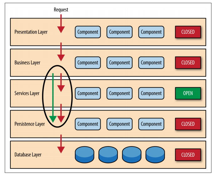
While closed layers facilitate layers of isolation and therefore help isolate change within the architecture, there are times when it makes sense for certain layers to be open. For example, suppose you want to add a shared-services layer to an architecture containing com‐ mon service components accessed by components within the busi‐ ness layer (e.g., data and string utility classes or auditing and logging classes). Creating a services layer is usually a good idea in this case because architecturally it restricts access to the shared services to the business layer (and not the presentation layer). Without a separate layer, there is nothing architecturally that restricts the presentation layer from accessing these common services, making it difficult to govern this access restriction.
Pattern Analysis
Overall agility Rating: Low Analysis: Overall agility is the ability to respond quickly to a constantly changing environment. While change can be isolated through the layers of isolation feature of this pattern, it is still cumbersome and time-consuming to make changes in this architecture pattern because of the monolithic nature of most implementations as well as the tight coupling of components usually found with this pattern.
Ease of deployment Rating: Low Analysis: Depending on how you implement this pattern, deployment can become an issue, particularly for larger applications. One small change to a component can require a redeployment of the entire application (or a large portion of the application), resulting in deployments that need to be planned, scheduled, and executed during off-hours or on weekends. As such, this pattern does not easily lend itself toward a continuous delivery pipeline, further reducing the overall rating for deployment.
Performance Rating: Low Analysis: While it is true some layered architectures can per‐ form well, the pattern does not lend itself to high-performance applications due to the inefficiencies of having to go through multiple layers of the architecture to fulfill a business request.
Scalability Rating: Low Analysis: Because of the trend toward tightly coupled and monolithic implementations of this pattern, applications build using this architecture pattern are generally difficult to scale. You can scale a layered architecture by splitting the layers into separate physical deployments or replicating the entire application into multiple nodes, but overall the granularity is too broad, making it expensive to scale.
Event Driven Architecture
The event-driven architecture pattern is a popular distributed asynchronous architecture pattern used to produce highly scalable applications. It is also highly adaptable and can be used for small applications and as well as large, complex ones. The event-driven architecture is made up of highly decoupled, single-purpose event processing components that asynchronously receive and process events.
The event-driven architecture pattern consists of two main topologies, the mediator and the broker.
- the mediator topology is commonly used when you need to orchestrate multiple steps within an event through a central mediato.
- the broker topology is used when you want to chain events together without the use of a central mediator.
Mediator Topology
The mediator topology is useful for events that have multiple steps and require some level of orchestration to process the event.
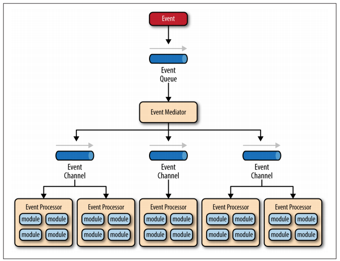
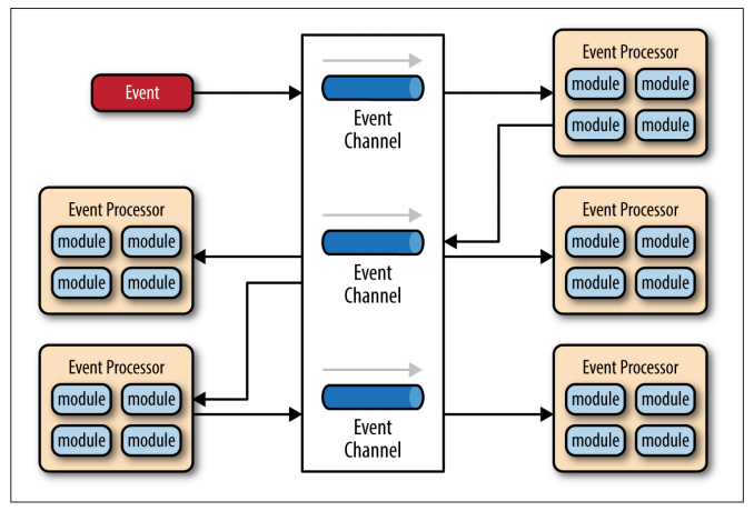
There are four main types of architecture components within the mediator topology: event queues, an event mediator, event channels, and event processors.
The event flow starts with a client sending an event to an event queue, which is used to transport the event to the event mediator. The event mediator receives the initial event and orchestrates that event by sending additional asynchronous events to event channels to execute each step of the process. Event processors, which listen on the event channels, receive the event from the event mediator and execute specific business logic to process the event.
The pattern does not specify the implementation of the event queue component; it can be a message queue, a web service endpoint, or any combination thereof
There are two types of events within this pattern: an initial event and a processing event. The initial event is the original event received by the mediator, whereas the processing events are ones that are generated by the mediator and received by the event-processing components.
The event channels can be either message queues(1 to 1) or message topics (1 to many), although message topics are most widely used with the mediator topology so that processing events can be processed by multiple event processors (each performing a different task based on the processing event received).
The simplest and most common implementation of the event mediator is through open source integration hubs such as Spring Integration, Apache Camel, or Mule ESB.
Example
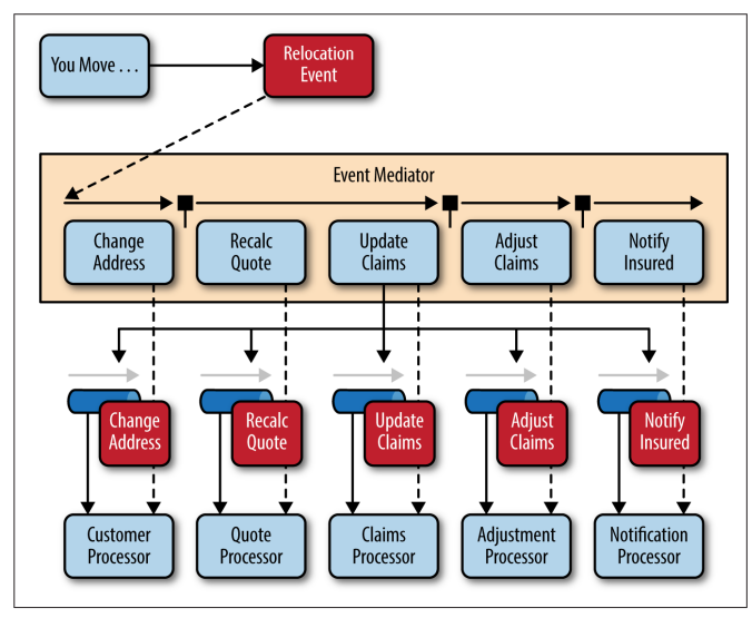
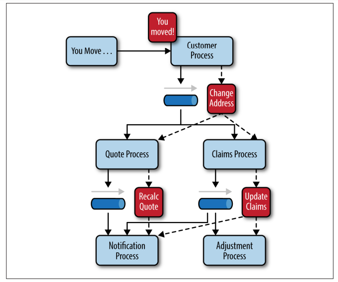
To illustrate how the mediator topology works, suppose you are insured through an insurance company and you decide to move. In this case, the initial event might be called something like relocation event.
The steps involved in processing a relocation event are contained within the event mediator.
- for each initial event step, the event mediator creates a processing event (e.g., change address, recalc quote, etc.)
- sends that processing event to the event channel and waits for the processing event to be processed by the corresponding event processor (e.g., customer process, quote process, etc.).
- this process continues until all of the steps in the initial event have been processed.
- the single bar over the recalc quote and update claims steps in the event mediator indicates that these steps can be run at the same time.
Broker Topology
The broker topology differs from the mediator topology in that there is no central event mediator; rather, the message flow is distributed across the event processor components in a chain-like fashion through a lightweight message broker (e.g., ActiveMQ, HornetQ, etc.). This topology is useful when you have a relatively simple event processing flow and you do not want (or need) central event orchestration.
The broker topology is all about the chaining of events to perform a business function.
Example
To illustrate how the broker topology works, we’ll use the same example as in the mediator topology (an insured person moves).
Since there is no central event mediator to receive the initial event in the broker topology:
- the customer-process component receives the event directly, changes the customer address, and sends out an event saying it changed a customer’s address (e.g., change address event).
- In this example, there are two event processors that are interested in the change address event: the quote process and the claims process.
- The quote processor component recalculates the new autoinsurance rates based on the address change and publishes an event to the rest of the system indicating what it did (e.g., recalc quote event).
- The claims processing component, on the other hand, receives the same change address event, but in this case, it updates an outstanding insurance claim and publishes an event to the system as an update claim event.
- These new events are then picked up by other event processor components, and the event chain continues through the system until there are no more events are published for that particular initiating event.
The broker topology is all about the chaining of events to perform a business function.
Considerations
The event-driven architecture pattern is a relatively complex pattern to implement, primarily due to its asynchronous distributed nature. When implementing this pattern, you must address various distributed architecture issues, such as remote process availability, lack of responsiveness, and broker reconnection logic in the event of a broker or mediator failure.
One consideration to take into account when choosing this architecture pattern is the lack of atomic transactions for a single business process. Because event processor components are highly decoupled and distributed, it is very difficult to maintain a transactional unit of work across them. For this reason, when designing your application using this pattern, you must continuously think about which events can and can’t run independently and plan the granularity of your event processors accordingly. If you find that you need to split a single unit of work across event processors—that is, if you are using separate processors for something that should be an undivided transaction—this is probably not the right pattern for your application.
Perhaps one of the most difficult aspects of the event-driven architecture pattern is the creation, maintenance, and governance of the event-processor component contracts. Each event usually has a specific contract associated with it (e.g., the data values and data format being passed to the event processor). It is vitally important when using this pattern to settle on a standard data format (e.g., XML, JSON, Java Object, etc.) and establish a contract versioning policy right from the start.
Testability Rating: Low Analysis: While individual unit testing is not overly difficult, it does require some sort of specialized testing client or testing tool to generate events. Testing is also complicated by the asynchronous nature of this pattern.
Ease of development Rating: Low Analysis: Development can be somewhat complicated due to the asynchronous nature of the pattern as well as contract cre‐ ation and the need for more advanced error handling condi‐ tions within the code for unresponsive event processors and failed brokers.
Microkernel/Plug-In Architecture
The microkernel architecture pattern (sometimes referred to as the plug-in architecture pattern) is a natural pattern for implementing product-based applications. A product-based application is one that is packaged and made available for download in versions as a typical third-party product
The microkernel architecture pattern allows you to add additional application features as plug-ins to the core application, providing extensibility as well as feature separation and isolation.
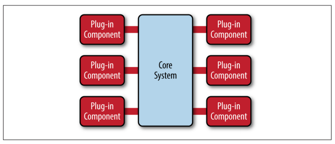
The core system needs to know about which plug-in modules are available and how to get to them. One common way of implementing this is through some sort of plug-in registry. This registry contains information about each plug-in module, including things like its name, data contract, and remote access protocol details (depending on how the plug-in is connected to the core system).
Plug-in modules can be connected to the core system through a variety of ways, including OSGi (open service gateway initiative), messaging, web services, or even direct point-to-point binding (i.e., object instantiation).
Example: Perhaps the best example of the microkernel architecture is the Eclipse IDE. Downloading the basic Eclipse product provides you little more than a fancy editor. However, once you start adding plug-ins, it becomes a highly customizable and useful product.
Considerations
Scalability Rating: Low Analysis: Because most microkernel architecture implementations are product based and are generally smaller in size, they are implemented as single units and hence not highly scalable. Depending on how you implement the plug-in modules, you can sometimes provide scalability at the plug-in feature level, but overall this pattern is not known for producing highly scala‐ ble applications.
Ease of development Rating: Low Analysis: The microkernel architecture requires thoughtful design and contract governance, making it rather complex to implement. Contract versioning, internal plug-in registries, plug-in granularity, and the wide choices available for plug-in connectivity all contribute to the complexity involved with implementing this pattern.
MicroServices Architecture
Core Concepts
- separately deployed units
- distributed architecture, meaning that all the components within the architecture are fully decoupled from one other and accessed through some sort of remote access protocol (e.g., JMS, AMQP, REST, SOAP, RMI, etc.)
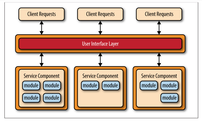
Service components contain one or more modules (e.g., Java classes) that represent either 27 a single-purpose function (e.g., providing the weather for a specific city or town) or an independent portion of a large business application (e.g., stock trade placement or determining auto-insurance rates). Designing the right level of service component granularity is one of the biggest challenges within a microservices architecture.
Api - REST Based Topology
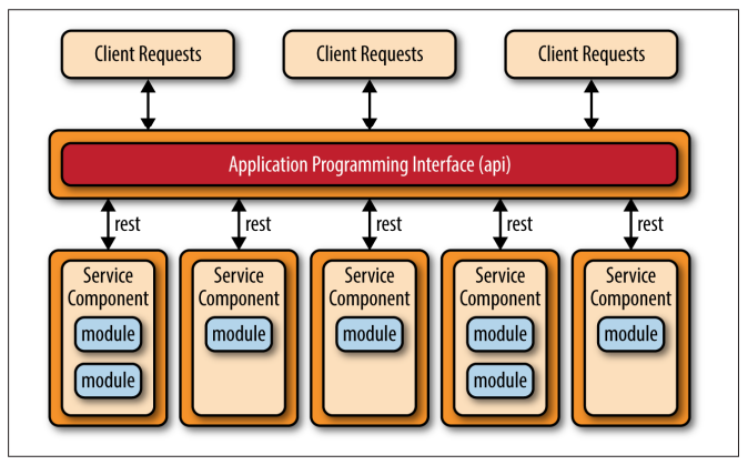
The API REST-based topology is useful for websites that expose small, self-contained individual services through some sort of API (application programming interface).
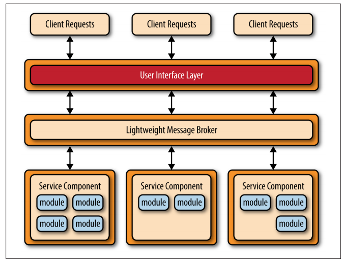
Centralized Messaging Topology
Another common approach within the microservices architecture pattern is the centralized messaging topology. This topology is similar to the previous application REST based topology except that instead of using REST for remote access, this topology uses a lightweight centralized message broker (e.g., ActiveMQ, HornetQ, etc.). It is vitally important when looking at this topology not to confuse it with the service-oriented architecture pattern or consider it “SOA-Lite." The lightweight message broker found in this topology does not perform any orchestration, transformation, or complex routing; rather, it is just a lightweight transport to access remote service components.
Considerations
Performance Rating: Low Analysis: While you can create applications implemented from this pattern that perform very well, overall this pattern does not naturally lend itself to high-performance applications due to the distributed nature of the microservices architecture pattern.
Space-Based Architecture
The space-based pattern (also sometimes referred to as the cloud architecture pattern) minimizes the factors that limit application scaling. This pattern gets its name from the concept of tuple space, the idea of distributed shared memory. High scalability is achieved by removing the central database constraint and using replicated in-memory data grids instead. Application data is kept in memory and replicated among all the active processing units. Processing units can be dynamically started up and shut down as user load increases and decreases, thereby addressing variable scalability. Because there is no central database, the database bottleneck is removed, providing near-infinite scalability within the application.
A tuple space is an implementation of the associative memory paradigm for parallel/distributed computing. It provides a repository of tuples that can be accessed concurrently.
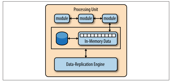
The processing unit typically contains the application modules, along with an in-memory data grid and an optional asynchronous persistent store for failover. It also contains a replication engine that is used by the virtualized mid‐ dleware to replicate data changes made by one processing unit to other active processing units.
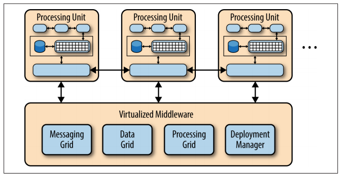
The virtualized-middleware component handles housekeeping and communications. It contains components that control various aspects of data synchronization and request handling. Included in the virtualized middleware are the messaging grid, data grid, processing grid, and deployment manager. These components, which are described in detail in the next section, can be custom written or purchased as third-party products.
There are four main architecture components in the virtualized middleware: the messaging grid, the data grid, the processing grid, and the deployment manager.
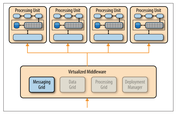
Messaging Grid
The messaging grid manages input request and session information. When a request comes into the virtualized middleware component, the messaging-grid component determines
- which active processing components are available to receive the request
- forwards the request to one of those processing units.
The complexity of the messaging grid can range from a simple round-robin algorithm to a more complex next-available algorithm that keeps track of which request is being processed by which processing unit.
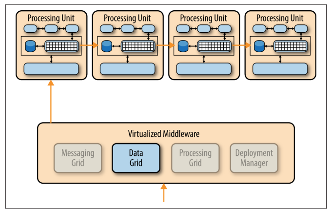
Data Grid
The data-grid component is perhaps the most important and crucial component in this pattern.
The data grid
- interacts with the data replication engine in each processing unit to manage the data replication between processing units when data updates occur.
Since the messaging grid can forward a request to any of the processing units available, it is essential that each processing unit contains exactly the same data in its in-memory data grid. Although the diagram below shows a synchronous data replication between processing units, in reality this is done in parallel asynchronously and very quickly, sometimes completing the data synchronization in a matter of microseconds (one millionth of a second).
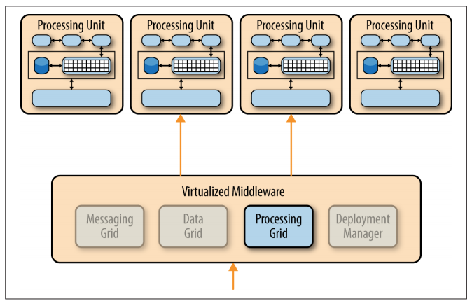
Processing Grid
The processing grid is an optional component within the virtualized middleware that manages distributed request processing when there are multiple processing units, each handling a portion of the application.
If a request comes in that requires coordination between processing unit types (e.g., an order processing unit and a customer processing unit), it is the processing grid that mediates and orchestrates the request between those two processing units.
Deployment Manager
The deployment-manager component
- manages the dynamic startup and shutdown of processing units based on load conditions.
- continually monitors response times and user loads, and starts up new processing units when load increases
- shuts down processing units when the load decreases.
It is a critical component to achieving variable scalability needs within an application.
Considerations
The space-based architecture pattern is a complex and expensive pattern to implement.
It is:
- a good architecture choice for smaller web-based applications with variable load (e.g., social media sites, bidding and auction sites).
- not well suited for traditional large-scale relational database applications with large amounts of operational data.
Testability Rating: Low Analysis: Achieving very high user loads in a test environment is both expensive and time consuming, making it difficult to test the scalability aspects of the application.
Ease of development Rating: Low Analysis: Sophisticated caching and in-memory data grid prod‐ ucts make this pattern relatively complex to develop, mostly because of the lack of familiarity with the tools and products used to create this type of architecture. Furthermore, special care must be taken while developing these types of architectures to make sure nothing in the source code impacts performance and scalability.
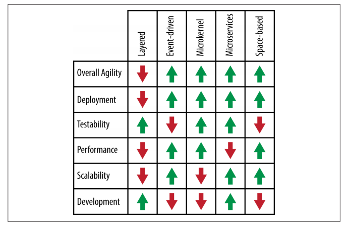
Pattern Analysis Summary
References
| Reference | URL |
|---|---|
| Software Architecture Patterns | https://github.com/gg-daddy/ebooks/blob/master/software-architecture-patterns.pdf |