Let’s look at the most fundamental transistor-switch circuit: an NPN switch. Here we use an NPN to control a high-power LED:
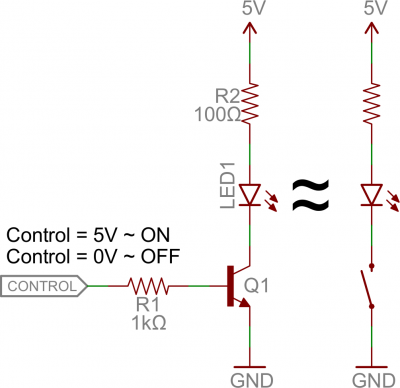
Our control input flows into the base, the output is tied to the collector, and the emitter is kept at a fixed voltage.
While a normal switch would require an actuator to be physically flipped, this switch is controlled by the voltage at the base pin. A microcontroller I/O pin, like those on an Arduino, can be programmed to go high or low to turn the LED on or off.
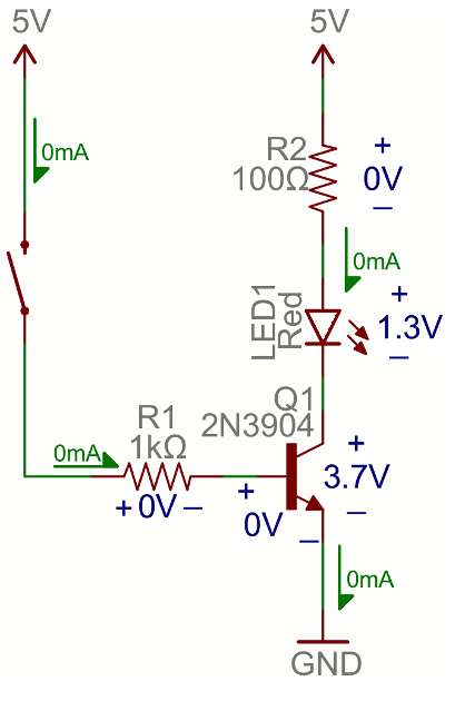
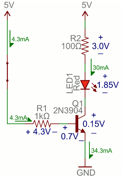
When the voltage at the base is greater than 0.6V (or whatever your transistor’s Vth might be), the transistor starts saturating and looks like a short circuit between collector and emitter. When the voltage at the base is less than 0.6V the transistor is in cutoff mode – no current flows because it looks like an open circuit between C and E.
The circuit above is called a low-side switch, because the switch – our transistor – is on the low (ground) side of the circuit. Alternatively, we can use a PNP transistor to create a high-side switch:
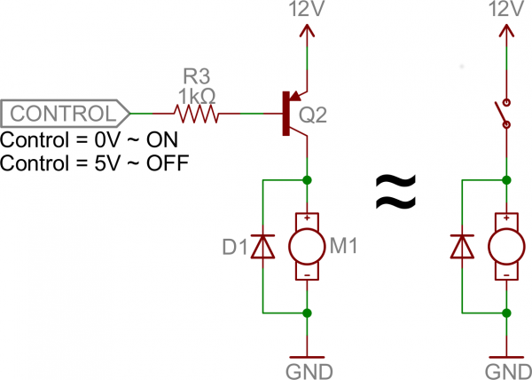
Similar to the NPN circuit, the base is our input, and the emitter is tied to a constant voltage. This time however, the emitter is tied high, and the load is connected to the transistor on the ground side.
This circuit works just as well as the NPN-based switch, but there’s one huge difference: to turn the load “on” the base must be low. This can cause complications, especially if the load’s high voltage (VCC in this picture) is higher than our control input’s high voltage. For example, this circuit wouldn’t work if you were trying to use a 5V-operating Arduino to switch on a 12V motor. In that case it’d be impossible to turn the switch off because VB would always be less than VE.
Base Resistors!
You’ll notice that each of those circuits uses a series resistor between the control input and the base of the transistor. Don’t forget to add this resistor! A transistor without a resistor on the base is like an LED with no current-limiting resistor.
Recall that, in a way, a transistor is just a pair of interconnected diodes. We’re forward-biasing the base-emitter diode to turn the load on. The diode only needs 0.6V to turn on, more voltage than that means more current. Some transistors may only be rated for a maximum of 10-100mA of current to flow through them. If you supply a current over the maximum rating, the transistor might blow up.
The series resistor between our control source and the base limits current into the base. The base-emitter node can get its happy voltage drop of 0.6V, and the resistor can drop the remaining voltage. The value of the resistor, and voltage across it, will set the current.
 .
. 
The resistor needs to be large enough to effectively limit the current, but small enough to feed the base enough current. 1mA to 10mA will usually be enough, but check your transistor’s datasheet to make sure.
References
| Reference | URL |
|---|---|
| Transistors as a Switch | https://learn.sparkfun.com/tutorials/transistors/applications-i-switches |