...
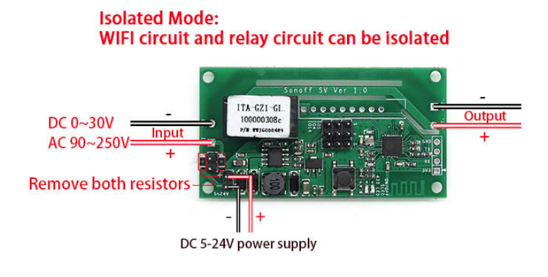
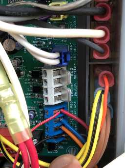
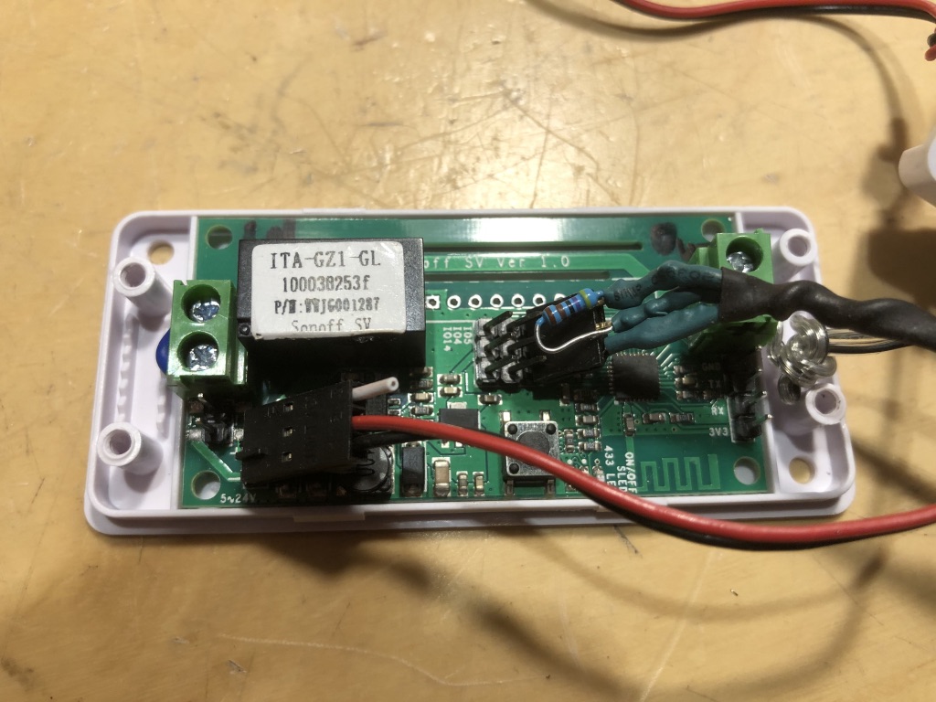
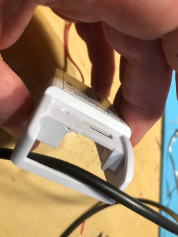
For this solution, we are using a Sonoff SV controller. This is a nice controller since it has everything we need to control the heater's remote relays. Additionally, we can power it from the heater itself since it accepts 5-24 volts input and the heater will supply us with 10v. We are going to use the Sonoff SV in isolation mode by removing the two resisters that would normally supply the power to the controller using the input voltage.
Wiring Diagram
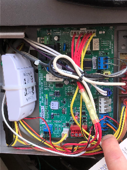
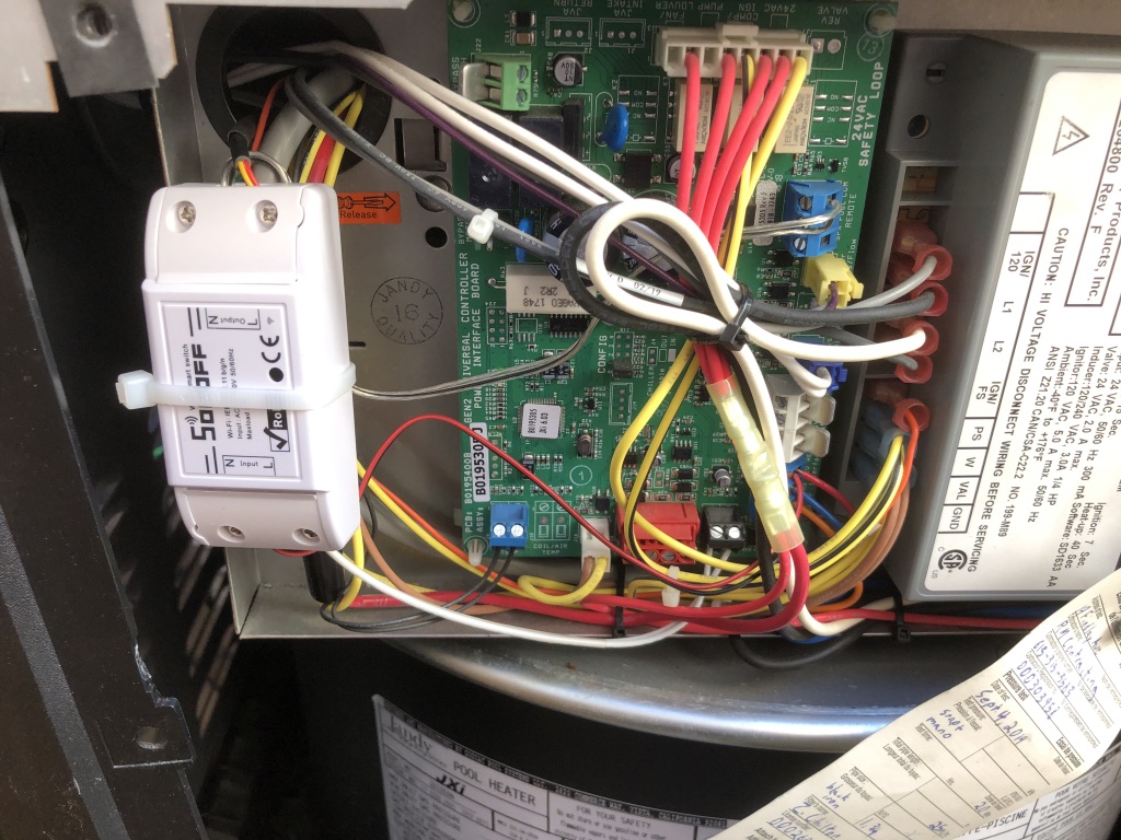
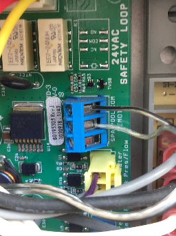
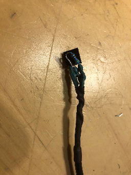
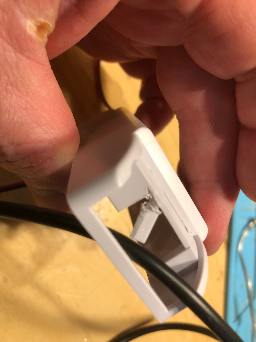
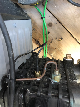
Pictures
Adding a Temperature Sensor
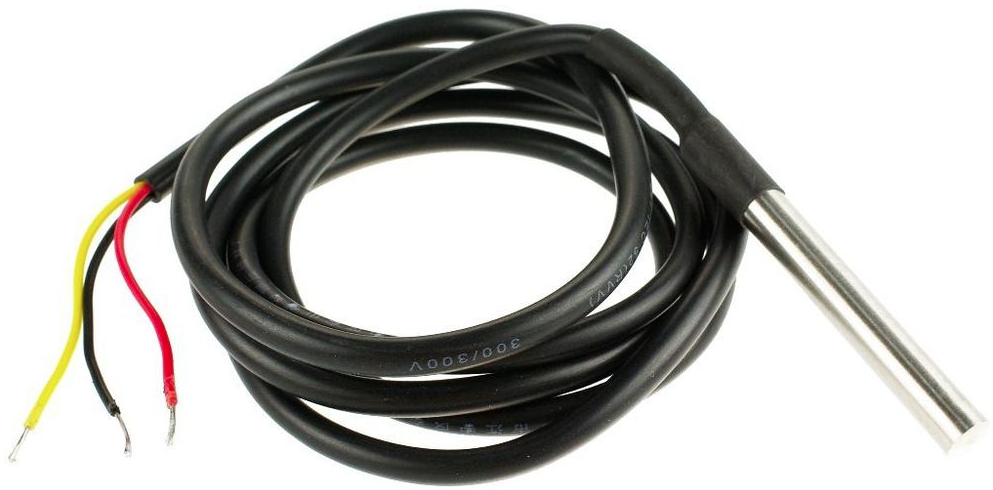
We are going to add a temperature sensor to the heater so that we can turn the heater on or off based on temperature.
We are going to use
- Waterproof Digital Temperature Temp Sensor Probe DS18b20
...
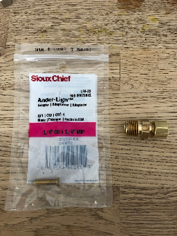
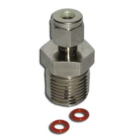
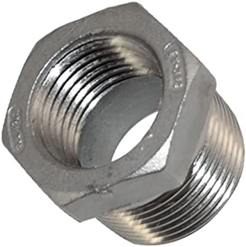
- a 1/4″ MIP to 1/
...
- 4" compression
...
- adaptor
- 2x 1/4" o-rings
...
3/4" male NTP to 1/2" female NTP adaptor
...
- teflon tape
For the 1/4" adaptor, some adjustments were needed.
We needed to
- drill out a metal piece on the compression cap in order to get the temperature probe through.
- drill out the body of the adaptor
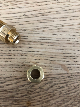
Once the drilling was done, we were able to pass the thermometer through the adaptor.
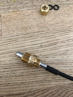
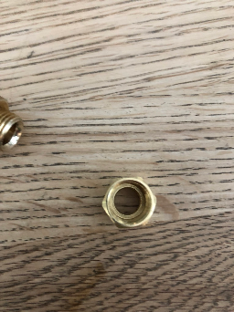
We added 2 x 1/4" o-rings for sealing the compression fitting to the temperature probe.
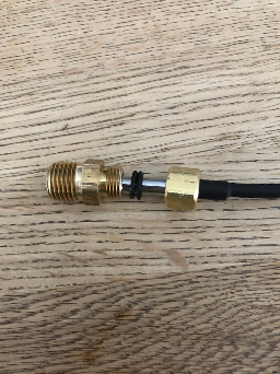
Put the temperature sensor, reducer and compression fitting together using teflon tape where needed.
<ADD PIC OF ASSEMBLED TEMP SENSOR>
We can add a temperature sensor to the heater's header using the following procedure:
- Turn off the power to the heater
- Remove drain plug from header and allow all water to drain from heat exchanger.
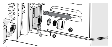
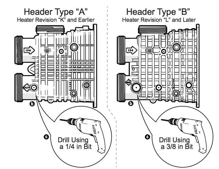
- Locate the threaded boss port on the outlet port inlet side of the header, and find the dimple at the center.
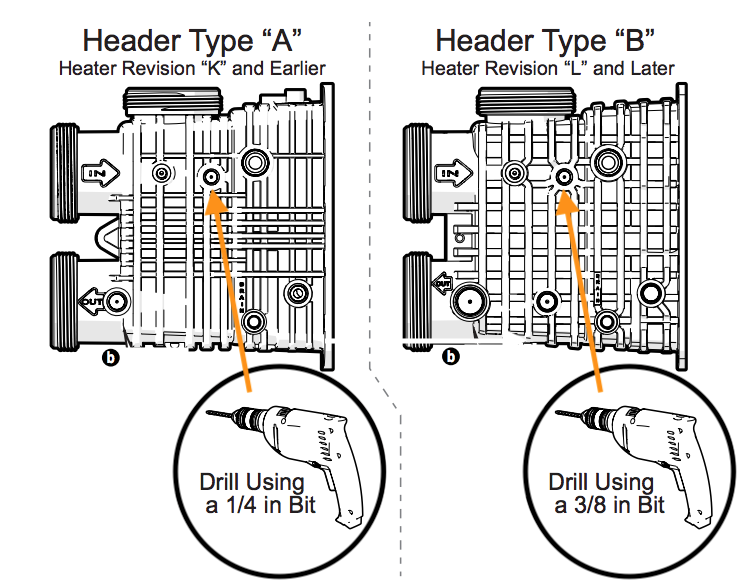
- Use the dimple to center the drill bit. For header type A: Drill a 1/4 in (6.4 mm) diameter hole through the boss. For header type B: Drill a 3/8 in (9.5 mm) diameter hole through the boss. port. Take care not to damage the plastic threads. TIP: Drilling a 1/8 in (3 mm) diameter hole first will help prevent thread damage.
- Wrapped Each male connection should be first wrapped in 5-6 turns of PTFE (Teflon) tape around the male threads of the adaptor.
- Install the temperature sensor assembled with any required reducers at the heater header. Make Thread in your 1/4 inch adaptor into the port. Make sure to get a snug fit. Do not over-tighten.

Homebridge Configuration
References
| Reference | URL |
|---|---|
| Jandy Heater Manuals | https://www.jandy.com/en/products/heaters/jxi Installation: https://www.jandy.com/-/media/zodiac/global/downloads/h/h0574300.pdf Installation Code Handbook: http://www.tagengineering.ca/wp-content/uploads/2015/02/B149-1handbook.pdf |
...