...
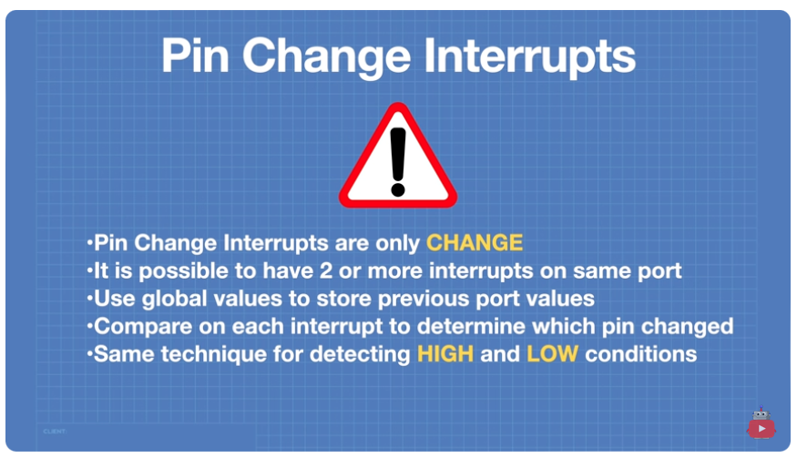
Note about Pin Change Interrupts
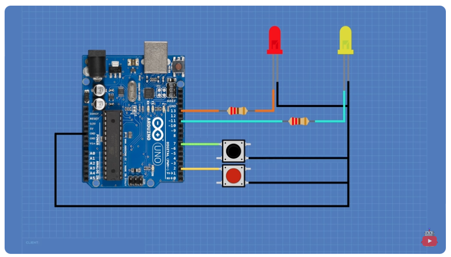
Circuit for Example Pin Change Interrupt
Sample Code
| Code Block | ||
|---|---|---|
| ||
// LEDs and switchs
const byte ledPin1 = 11;
const byte ledPin2 = 13;
const byte buttonPin1= 2;
const byte buttonPin2 = 7;

// Booleans for input states
volatile bool D2_state = LOW;
volatile bool D7_state = LOW;

void setup() {

  // Set LEDs as output
  pinMode(ledPin1, OUTPUT) ;
  pinMode(ledPin2, OUTPUT) ;

  // Set Switches as input with pullup
  pinMode(buttonPin1, INPUT_PULLUP) ;
  pinMode(buttonPin2, INPUT_PULLUP) ;

  // Enable PCIE2 Bit3 = 1 (Port D)|
  PCICR |= 800000100;

  //Enable interrupt on Pin D2 & D7 - Select PCINT18 & PCINT23 (Pin D2 & D7)
  PCMSK2 |= B10000100;
}

void loop(){
 // No code in Loop
}

ISR (PCINT2_vect)
{
  // Port D Interrupt occured

  // Check if this was D2
  if (digitalRead(buttonPin1) == LOW) {

    //Pin D2 triggered the ISR on a Falling pulse
    D2_state = !D2_state;

    //Set LED 1 to state of D2 state boolean
    digitalWrite(ledPin1, D2_state);
  }

  // Check if this was D7
  if (digitalRead(buttonPin2) == LOW) {

    //Pin D7 triggered the ISR on a Falling pulse
    D7_state = !D7_state;
    //Set LED 2 to state of D7_state boolean
    digitalWrite(ledPin2, D7_state);
  }

} |
Analyzing the Following Code
...