
| Table of Contents |
|---|
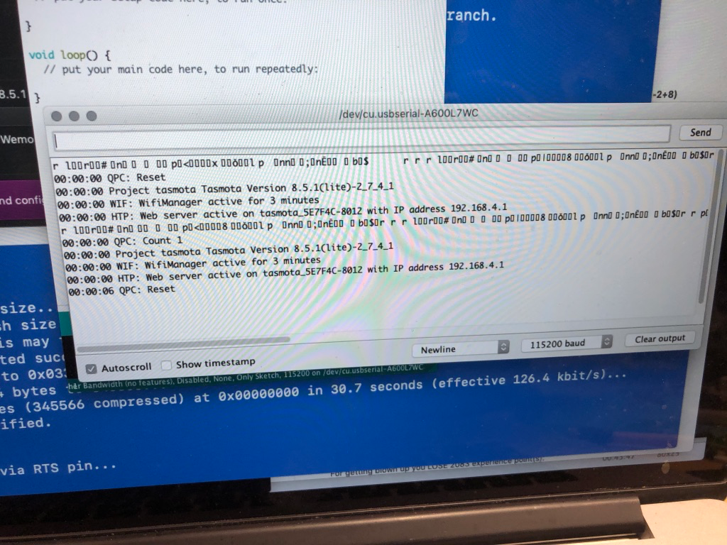
Flashing Tasmota
Overview
We are hoping to flash Tasmota firmware on our Treatlife DS01C Dimmer switch.
Version 1
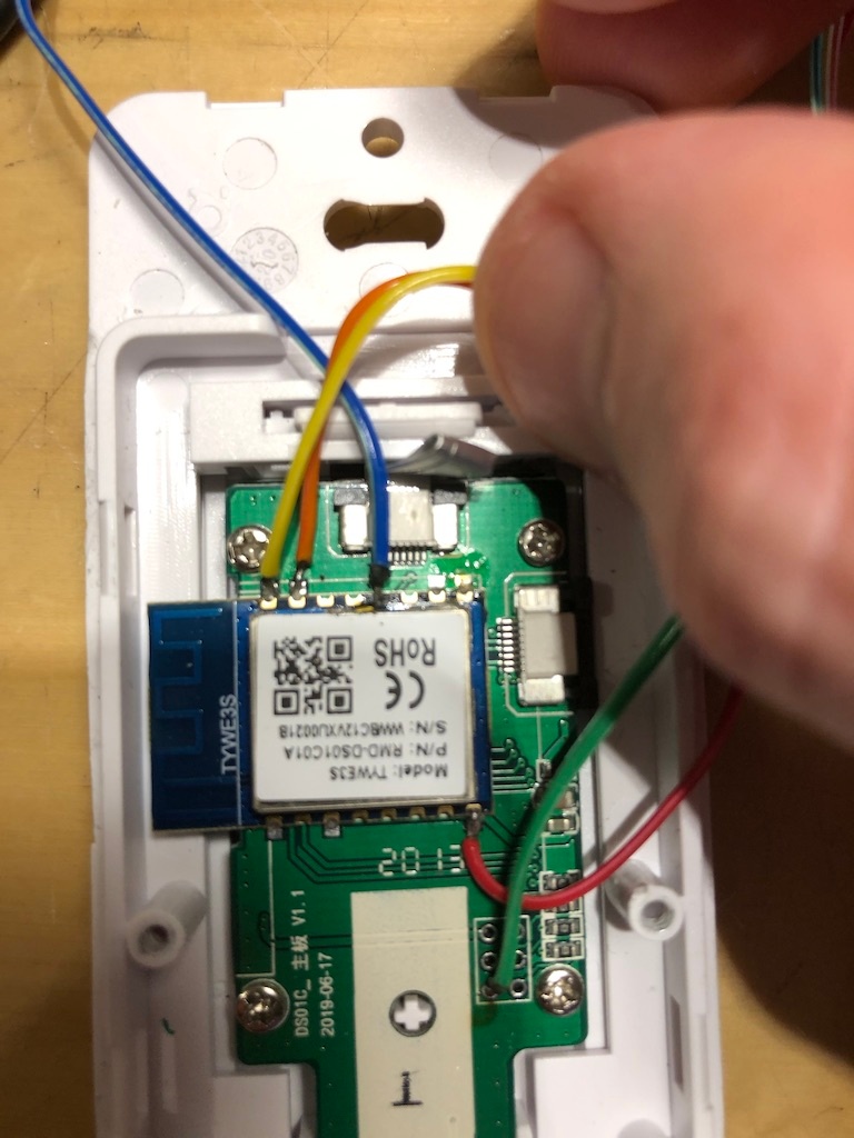
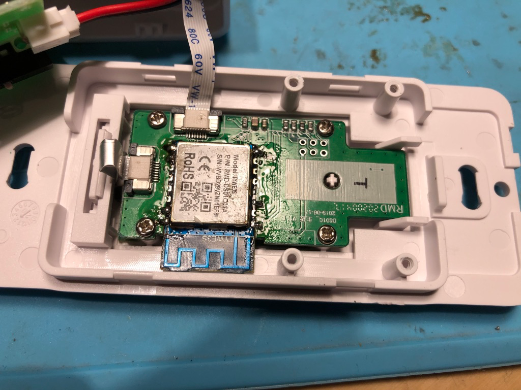
The initial Treatlife DS01 used The Treatlife DS01 uses a TYWE3S Chip (ESP8266):
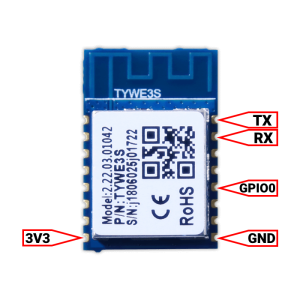
TYWE3S Wiring for Flashing
Vcc - 3.3V
TX - RX
RX - TX
GND - GND
Make sure to ground GPIO0 during boot.
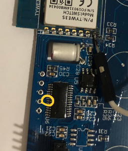
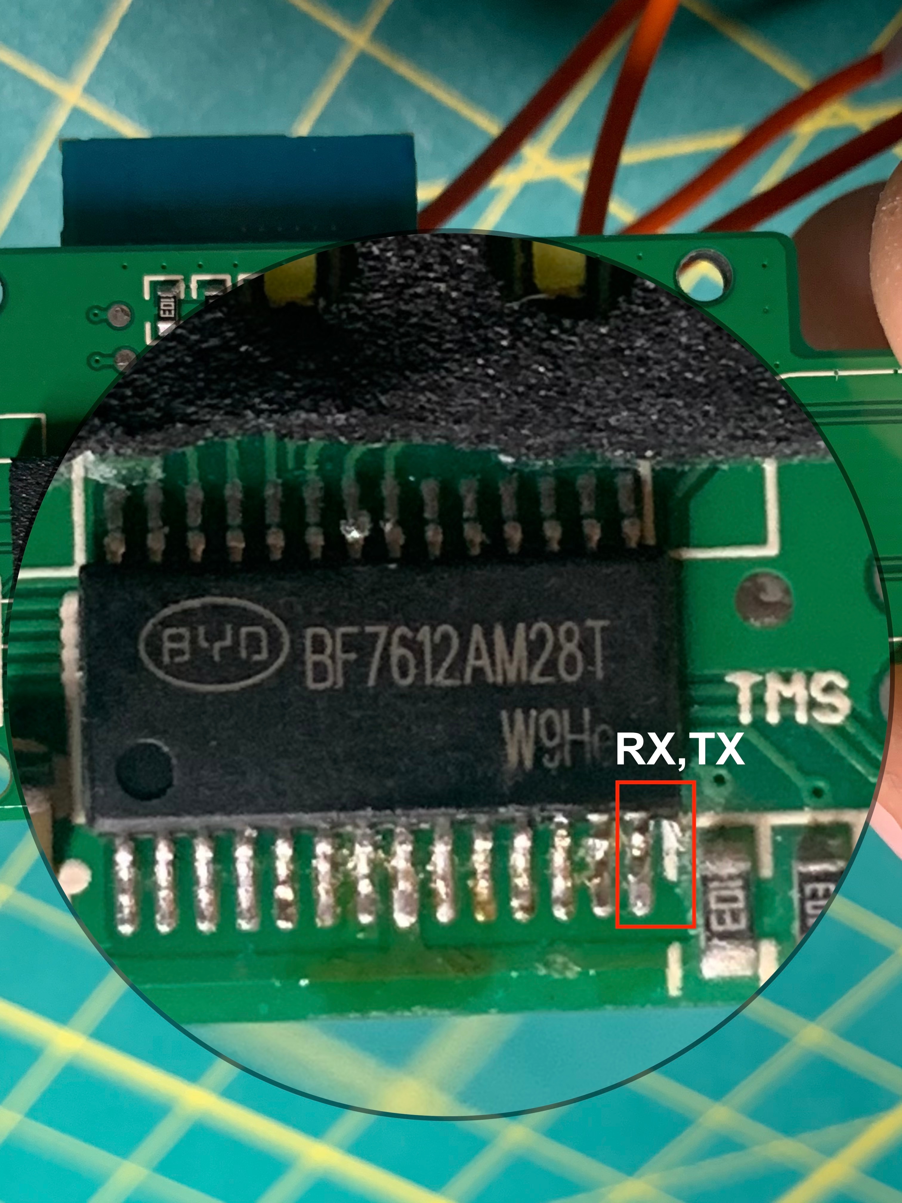
This dimmer has an MCU connected to the TYWE3S over the RX/TX pins.
MCU: MCU BYD - BF7612AM28T W9He
BF7612AMXXE-CN-MCU-Datasheet
TO TRY:
When flashing:
You need to ground RST, GPIO0 to start. after 3 seconds release RST. after another 3 seconds, release gpio0.
Flashing - Preparation
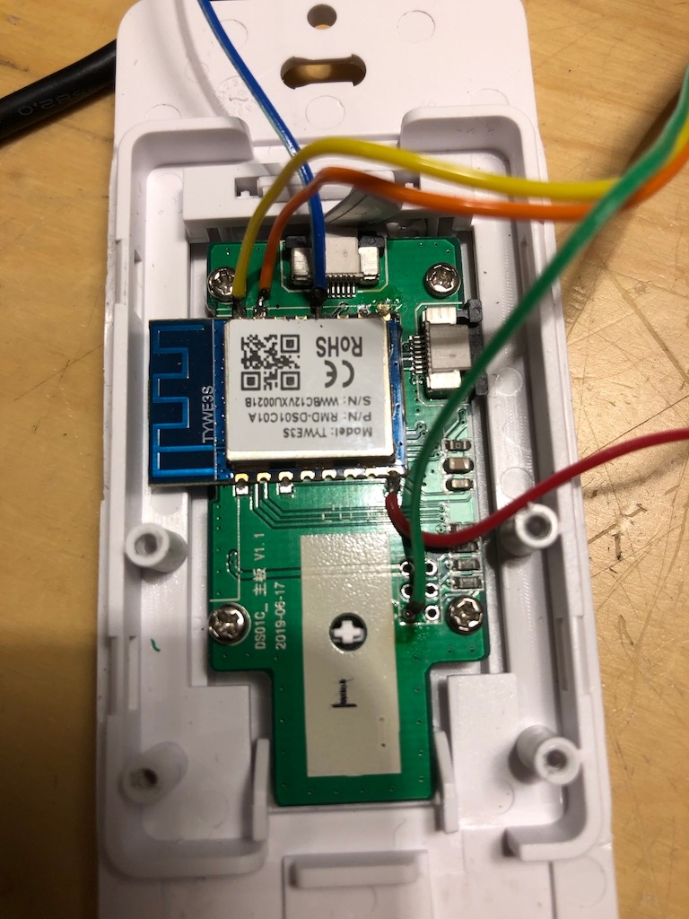
To boot the TYWE3S in flashing mode, GPIO0 needs to be connected to GND while powering up. It can be left grounded for the entire process. Flashing a TYWE3S connected to a MCU is a bit trickier than one without MCU. This is due the same Rx Tx pins used by MCU and serial programmer for flashing. The TYWE3S cannot be booted to flash mode with MCU sending data over the same pins. To be able to do that, we need to disable MCU from sending data over Rx and Tx pins. There are few ways to do it:
1. Disconnect TYWE3S module from the rest of board. (Naah, too much work) 2. Just break the Rx track from MCU to TYWE3S, flash and then reconnect. (Messy work, we want cleaner approach) 3. Just keep MCU disabled while flashing TYWE3S without any soldering / cutting. (We like that)
The easiest is to keep MCU disabled is by identifying the NRST/RST (Reset) pin of the MCU from its datasheet and connect it to GND for the entire flashing process. This will keep MCU disabled while you flash TYWE3S. If there are some contacts or test points in switches that connect to the MCU, you might be lucky to find contacts for RST that you can easily solder onto.
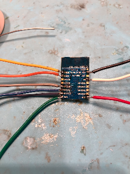
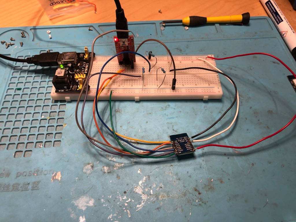
Pictures
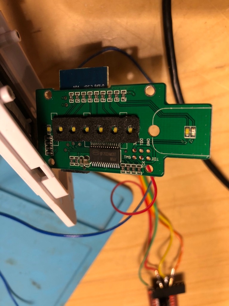
Tracing
Flashing
This chip is essentially an ESP8266. The ESP-12 Chip has the same pinout.
We can desolder the TYWE3S board and flash it just like we would an ESP-12.

To flash the ESP-12, you would need to connect it up as follows:
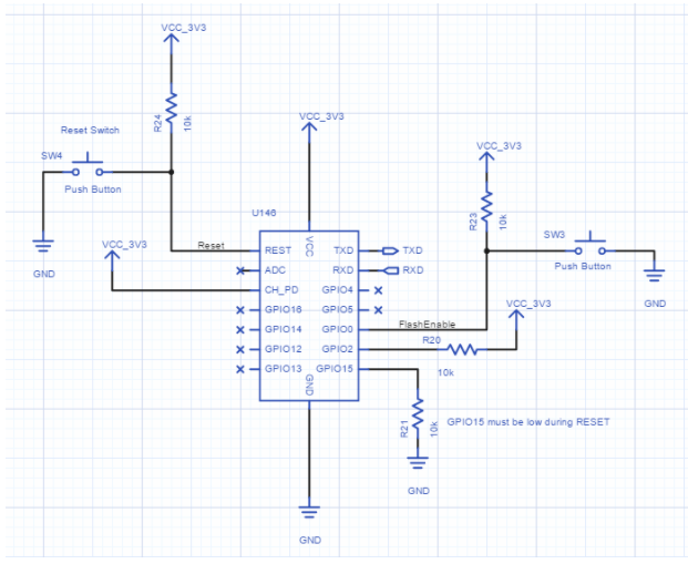
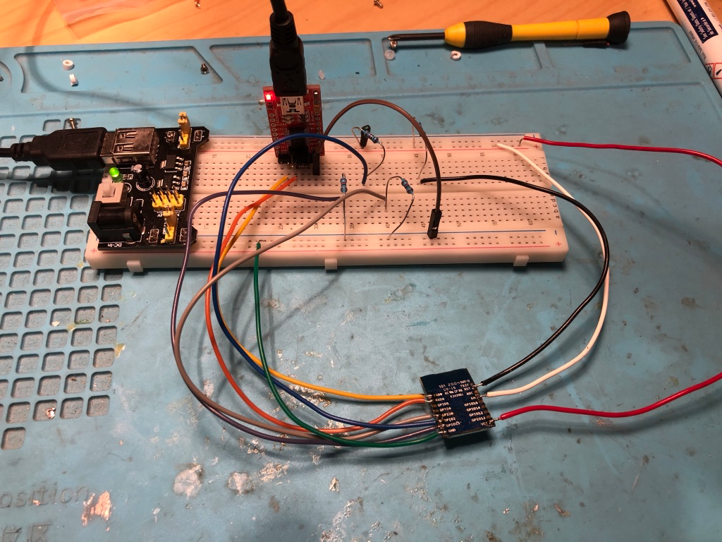
Ground GPIO-0 and power up the chip to enter programming mode.
We will flash the chip using Tasmotizer.
See https://github.com/tasmota/tasmotizer
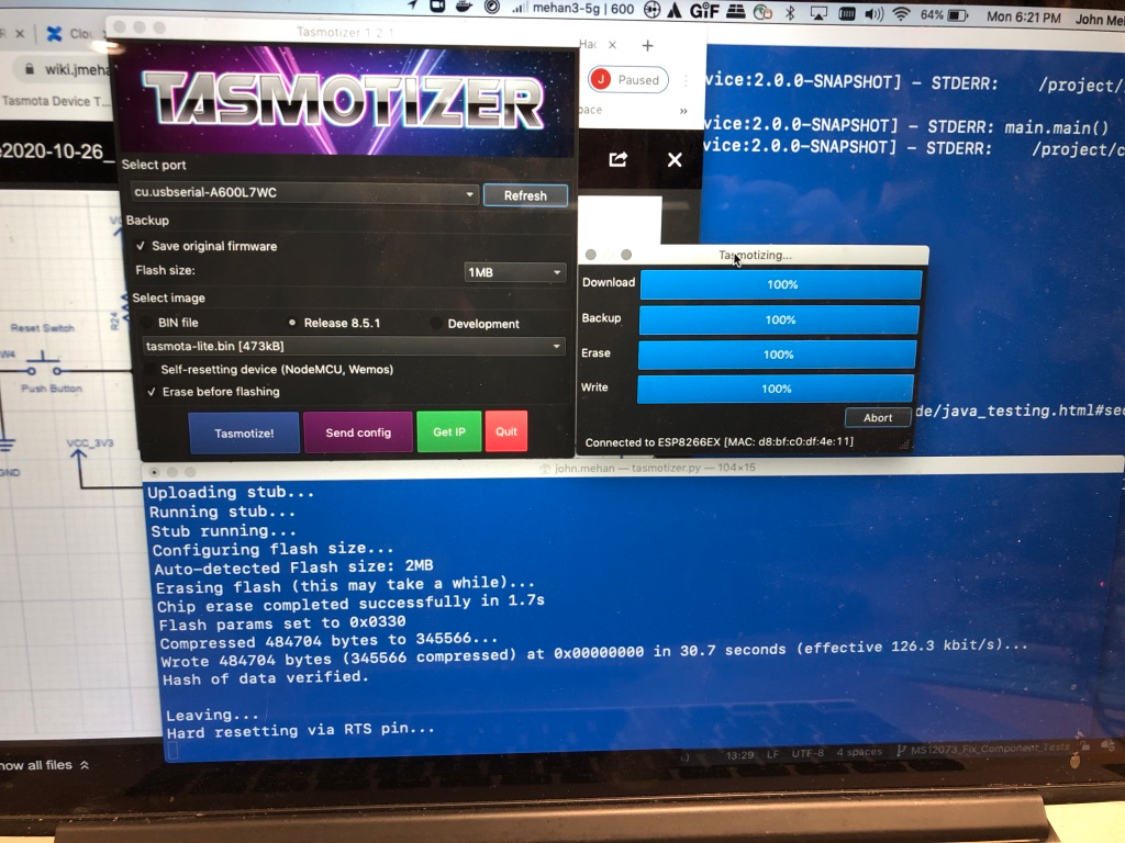
Disconnect GPIO-0 from ground and toggle power to boot
Re-assemble
Version 2
A newer version uses a custom chip which is not an ESP8266
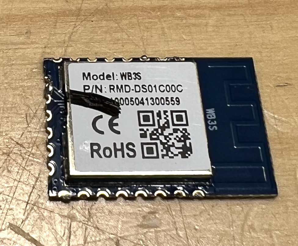
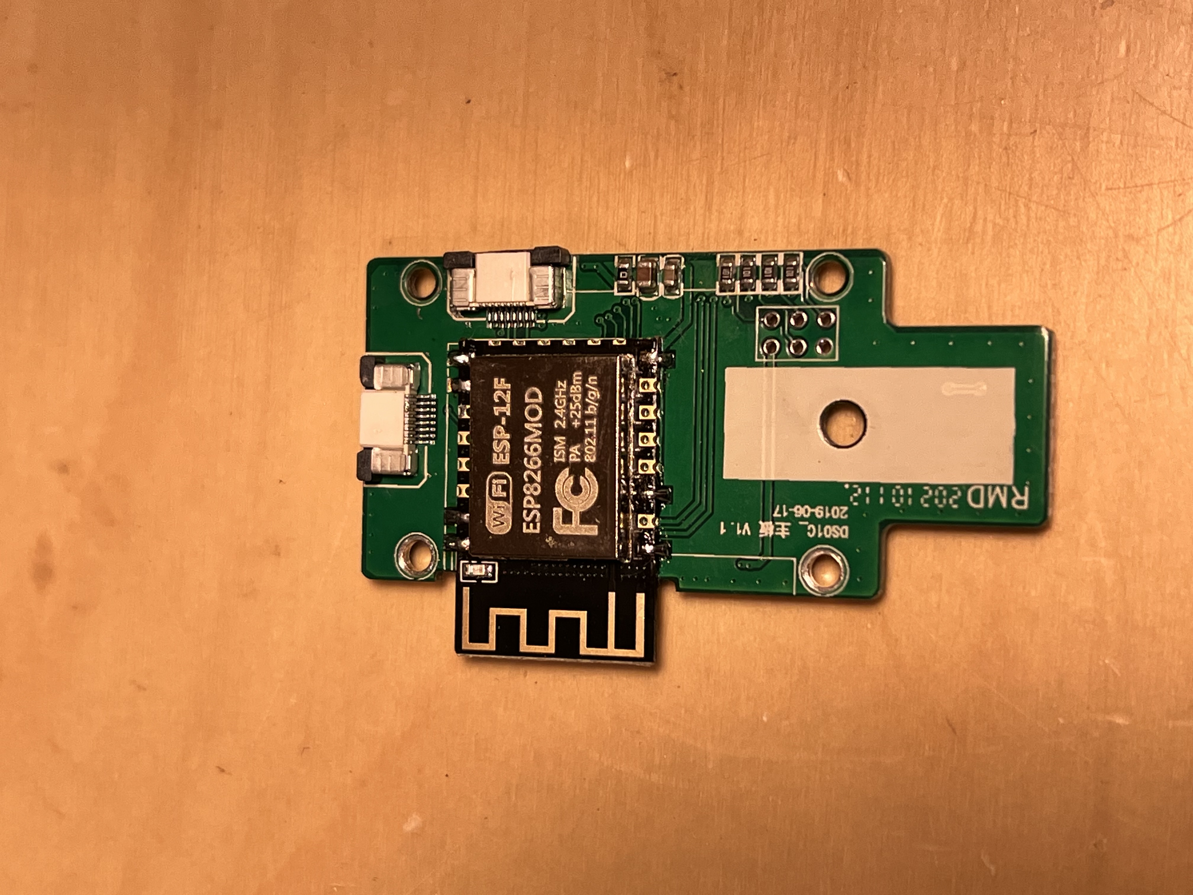
For this version we will de-solder the chip and replace it with an ESP8266 (ESP-12F)
Flashing
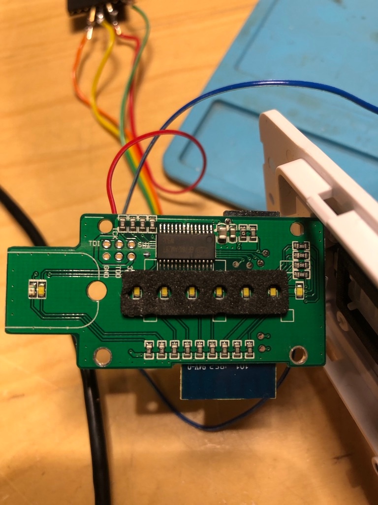
We can flash the board using the same procedure outlined for version 1. However, I decided to buy a new product to make flashing easier.
Wishiot ESP8266 Burning Fixture Development Board Micro USB Port Onboard CP2102 Chip Support ESP-01S ESP-07 ESP-07S ESP-12E ESP-12F ESP-12S ESP-C2 Easy Programer
https://www.amazon.ca/dp/B08BXMGVNM?psc=1&ref=ppx_yo2ov_dt_b_product_details
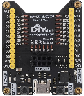
Just pop your ESP-12F into the board and flash using Tasmotizer.
After flashing, solder the board back onto the board.
Finished Board with new ESP-12F chip installed.
Configuring
Configuration is the same for both versions.
https://templates.blakadder.com/treatlife_DS01.html
From the console, issue the following commands:
| Code Block |
|---|
TuyaMCU 21,2
dimmerrange 150,1000
Rule1 on system#boot do SerialSend5 55AA00060005040400010114 endon
Rule 1 1 |
All Done!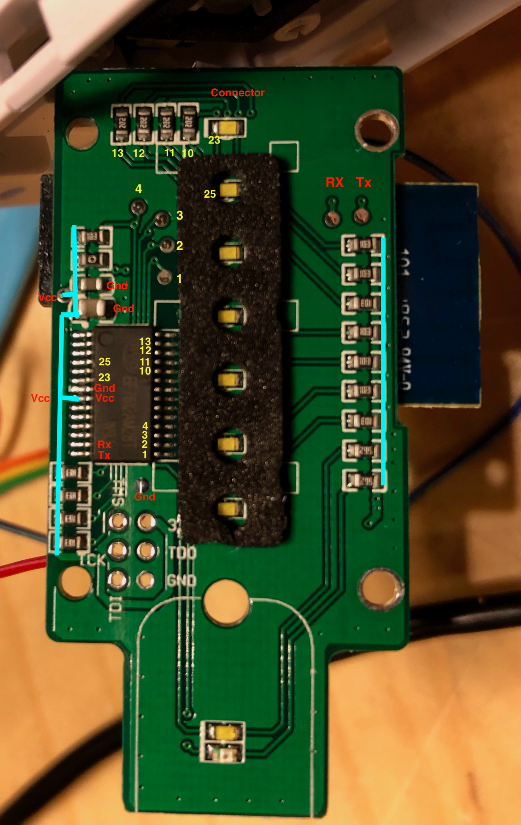
References
| Reference | URL |
|---|---|
| Tasmota - Tuya MCU Devices | https://tasmota.github.io/docs/TuyaMCU-Devices/ |
| Tasmota - TuyaMCU | https://tasmota.github.io/docs/TuyaMCU/ |
| Tasmota - TuyaMCU Protocol | https://tasmota.github.io/docs/TuyaMCU/#tuya-protocols |
| Tasmota Rules | https://tasmota.github.io/docs/Rules/ |
Trying to flash tasmota on TYWE3S #5377 | https://github.com/arendst/Tasmota/issues/5377 |
| Configuring Tasmota on DS01 | https://templates.blakadder.com/treatlife_DS01.html |