A lot of the capacitors you see in circuits, especially those featuring an integrated circuit, are decoupling. A decoupling capacitor’s job is to suppress high-frequency noise in power supply signals. They take tiny voltage ripples, which could otherwise be harmful to delicate ICs, out of the voltage supply.
In a way, decoupling capacitors act as a very small, local power supply for ICs (almost like an uninterupptable power supply is to computers). If the power supply very temporarily drops its voltage (which is actually pretty common, especially when the circuit it’s powering is constantly switching its load requirements), a decoupling capacitor can briefly supply power at the correct voltage. This is why these capacitors are also called bypass caps; they can temporarily act as a power source, bypassing the power supply.
Decoupling capacitors connect between the power source (5V, 3.3V, etc.) and ground. It’s not uncommon to use two or more different-valued, even different types of capacitors to bypass the power supply, because some capacitor values will be better than others at filtering out certain frequencies of noise.
Best Practices
The most simple incarnation of the bypass capacitor is a cap connected directly to the power source and to ground.
This simple connection will allow the AC component of VCC to pass through to ground. The cap acts like a reserve of current. The charged capacitor helps to fill in any 'dips' in the voltage VCC by releasing its charge when the voltage drops. The size of the capacitor determines how big of a 'dip' it can fill. The larger the capacitor, the larger the 'dip' it can handle. A common size to use is a .1uF capacitor. You will also see .01uF as a common value. The precise value of a bypass cap isn't very important.
So, how many bypass capacitors do you really need? A good rule of thumb is each IC on my board gets its own bypass capacitor. In fact, I try to place the bypass cap so it is directly connected to the Vcc and Gnd pins.
Another great place for a bypass cap is on power connectors. Anytime you have a power line heading off to another board or long wire, I would recommend putting in a bypass cap. Any long length of wire is going to act like a little antenna. It will pick up electrical noise from any magnetic field. I always put a bypass cap on both ends of such lengths of wire.
The type of capacitor you use can be important. It is recomended that you use a monolithic ceramic capacitor. They are small, cheap, and readily available. I usually use a .1uF 50Volt +-20% with .1" or .2" spacing. Again, .01uF is also acceptable. Avoid larger voltage capacitors as they are physically too large. Electrolytic capacitors are not well suited to the role of bypass capacitors as they typically have larger capacitance values and don't respond as well to high frequency changes.
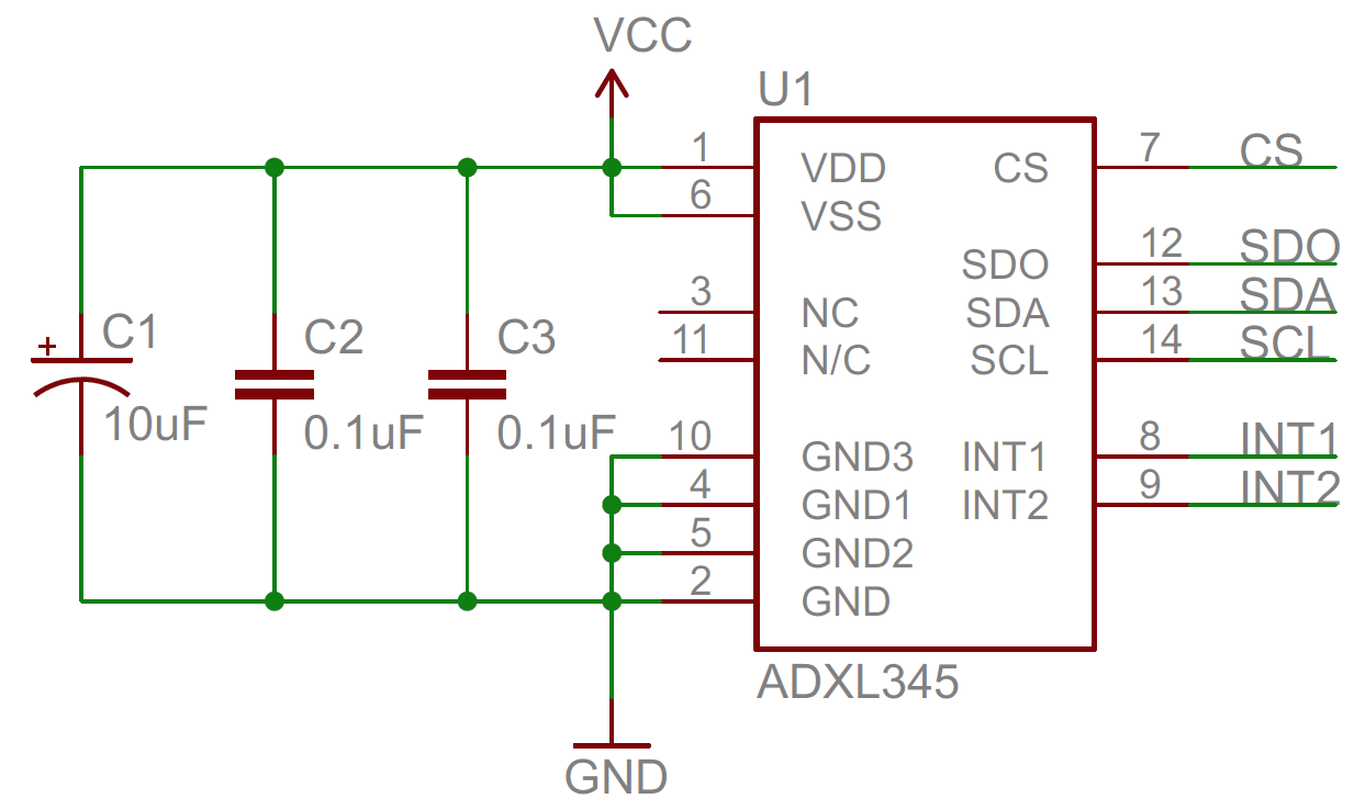
| The frequency of the ripple can have a role in choosing the capacitor value. Rule of thumb is the higher the frequency, the smaller the bypass capacitor you need. If you have very high frequency components in your circuit, you might consider a pair of capacitors in parallel. One with a large value, one with a small value. If you have very complex ripple, you may need to add several bypass capacitors. Each cap is targeting a slightly different frequency. You may even need to add a larger electrolytic cap in case the amplitude of the lower frequencys is too great. For example, the circuit on the right is using three different capacitor values in parallel. Each will respond better to different frequencies. The 4.7uF cap (C4) is used to catch larger voltage dips which are at relatively low frequencies. The cap C2 should be able to handle the midrange frequencies, and C3 will handle the higher frequencies. The frequency response of the capacitors is determined by their internal resistance and inductance. |
References
| Reference | URL |
|---|---|
| Wikipedia | https://en.wikipedia.org/wiki/Applications_of_capacitors |
| Sparkfun - Capacitors | https://learn.sparkfun.com/tutorials/capacitors |
| Filter Capcitor | |
| Using Bypass Capacitors |