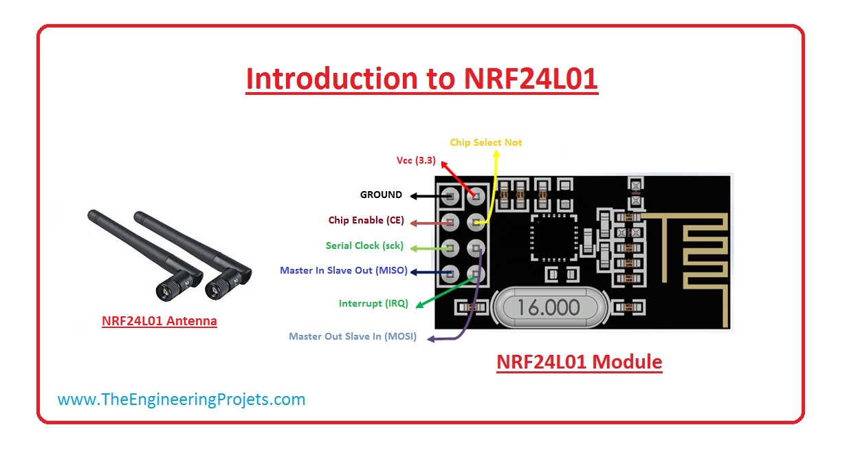
nRF24L01 is a single chip radio transceiver for the world wide 2.4 - 2.5 GHz ISM band. The transceiver consists of a fully integrated frequency synthesizer, a power amplifier, a crystal oscillator, a demodulator, modulator and Enhanced ShockBurst™ protocol engine.
Output power, frequency channels, and protocol setup are easily programmable through a SPI interface. Current consumption is very low, only 9.0mA at an output power of -6dBm and 12.3mA in RX mode. Built-in Power Down and Standby modes makes power saving easily realizable.
Board
Communicating with the Board
This board uses SPI, Serial Peripheral Interface.
The SPI bus specifies four logic signals:
- SCLK: Serial Clock (output from master)
- MOSI: Master Output Slave Input, or Master Out Slave In (data output from master)
- MISO: Master Input Slave Output, or Master In Slave Out (data output from slave)
- SS: Slave Select (often active low, output from master)
Hookup
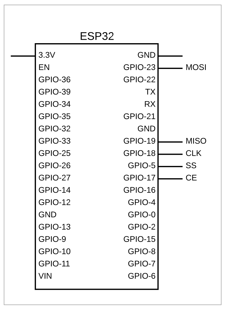
2- Use the following ESP32 pin configuration for pairing ESP32 to nRF24L01+
CE -> GPIO17 GPIO
CSN -> GPIO05 VSPI SS
MISO -> GPIO19 VSPI MISO
MOSI -> GPIO23 VSPI MOSI
CLK -> GPIO18 VSPI CLK
IRQ-> unconnected
Sample TX Code
#include <SPI.h>
#include "RF24.h"

/*
 * Commands
 * B - Left
 * C - Driver Door
 * D - Right
 * E - Back
 * F - Passenger Door?
 * G - Forward
 *
 *
 * Pinout
 *
 * CLK    18
 * MOSI   23
 * MISO   19
 * CS     5
 * CE     17
 */

#define CE_PIN    17
#define CS_PIN    5


RF24 radio(CE_PIN,CS_PIN);

//const byte pipes[2][6] = {"i8-001", "I8-001"};
//const byte addresses[2][6] = {{'i','8','-','0','0','1'},{'I','8','-','0','0','1'}};

const byte addresses[2][6] = {{0x69,0x38,0x2d,0x30,0x30,0x31},{0x49,0x38,0x2d,0x30,0x30,0x31}};
char buf[1];
int bufsize=1;

void setup() {
  Serial.begin(115200);
  Serial.println(F("\n\ni8 Tx Started"));
  Serial.println(F("*** PRESS 'B-G' to represent button"));

  radio.begin();

  // Set the PA Level low to prevent power supply related issues.
  radio.setPALevel(RF24_PA_LOW);

  radio.setRetries(15,15);
  radio.setPayloadSize(8);
  radio.setDataRate(RF24_1MBPS);
  radio.setAutoAck(1);                     // Ensure autoACK is enabled

  radio.openWritingPipe(addresses[0]);
  radio.stopListening();

}

void loop() {

  // process serial requests
  if ( Serial.available() )
  {
    char c = toupper(Serial.read());
    //'B', 'C', 'D', 'E', 'F', 'G'
    if(c >= 'B' && c <= 'G'){
      Serial.printf("> %c \n",c);

      buf[0]=c;
      int v = radio.write(&buf, bufsize);

      buf[0]=tolower(c);
      v = radio.write(&buf, bufsize);
    }
  }

}
References
| Reference | URL |
|---|---|
| Spec | https://www.sparkfun.com/datasheets/Components/nRF24L01_prelim_prod_spec_1_2.pdf |
| Tutorial | https://howtomechatronics.com/tutorials/arduino/arduino-wireless-communication-nrf24l01-tutorial/ |
| Demo 41: ESP32 connects with nRF24L01 2.4 GHz wireless chip | http://www.iotsharing.com/2018/03/esp-and-raspberry-connect-with-nrf24l01.html |