Overview
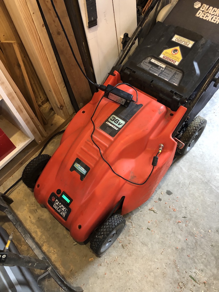
Black and Decker CM1836

Charging
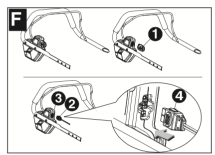
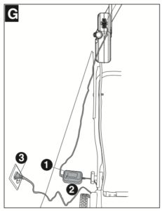
CHARGING PROCEDURE- FIGURES F & G
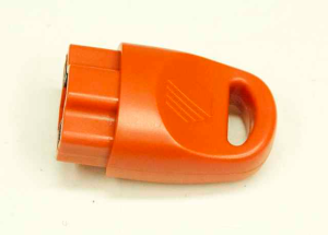
1. Remove safety key F- 1
2. Align the charger plug F-2 with the arrow F-4 on top and insert the charger plug into the receptacle F-3 on the mower (green terminal to green terminal, white terminal to white terminal). The charger connector can only b e plugged into the mower receptacle one way.
3. Insert the 120 volt plug G-3 of the charger G-1 into the wall receptacle.
4. The red light G- 2 on the charger should come on indica ting you have power and the battery is being charged.
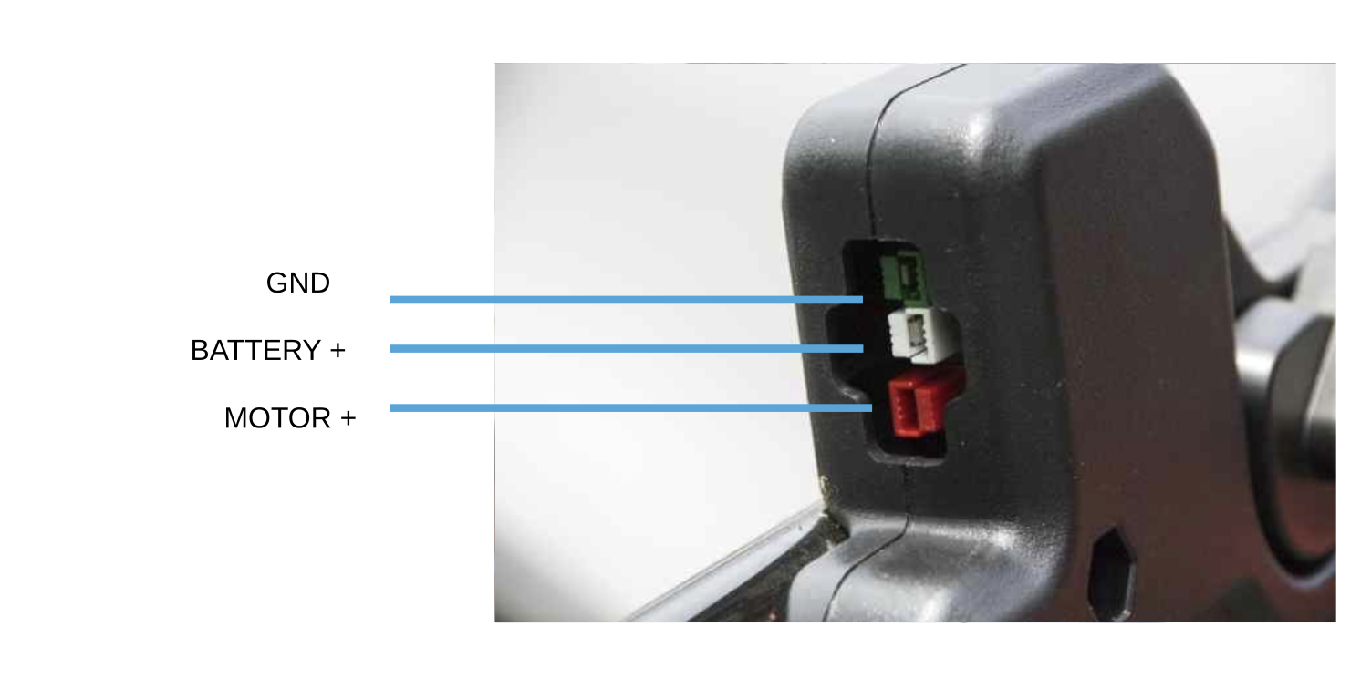
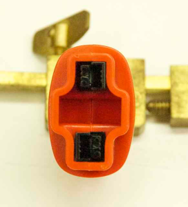
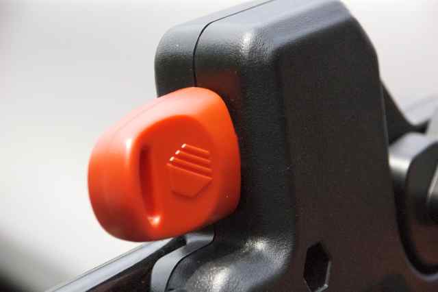
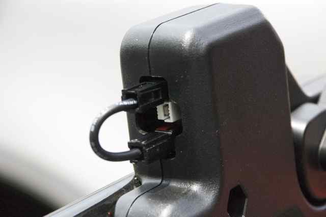
Safety Key
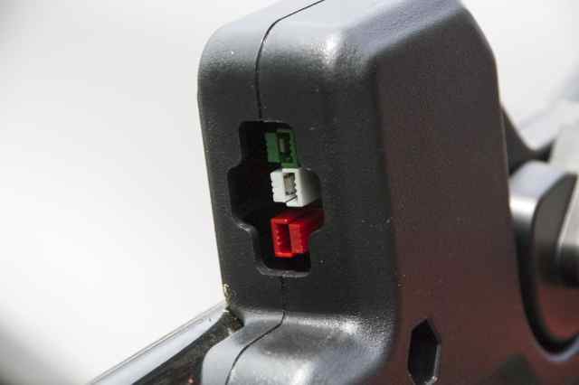
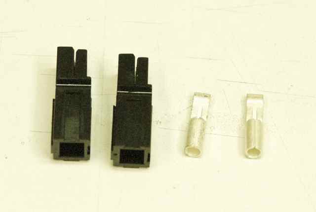
The safety key that comes with the CM/SPCM1936 installs in the safety key/charging port near the top of the handle. The key works by making/breaking the power connection between the top and bottom connectors. The third connector in the middle is for charging.
If the safety key is lost, it is possible to make a shorting lead from some 30A Anderson PowerPole connectors and a short piece of 12-14AWG wire if you have the right crimp tools or soldering skills. However, you are much better off getting another key as this fix DOES NOT STOP YOU FROM ACCIDENTALLY CONNECTING THE WRONG TWO CONNECTORS AND SHORTING THE BATTERY. I'm not sure what happens next if the wrong connection is made - maybe a breaker trips or maybe some wires melt - not good things! But this can get you going in a pinch if you are stuck and only costs a couple of bucks to implement.
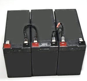
Battery
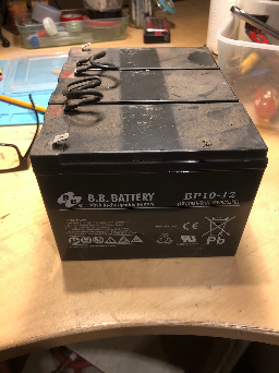
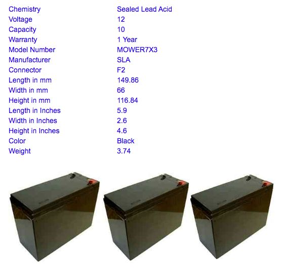
Total size of the three batteries together
| Width | 3*66 = 198 mm |
|---|---|
| Length | 149 mm |
| Height | 117 mm |
Replacing the Batteries
1. First use compressed air to blow out the six screw holes that secure the cover to the chassis. If, like me, you don't have a compressor, just tip the mower over so gravity will allow the dead grass and chaff that fills up the screw wells over time to fall out as you dislodge the stuff with a screw driver or a stick.
2. After the debris is removed, use a T20 Torx driver to loosen the screws. There is a slot in the cover screws that allow the use of a blade screwdriver, but you'll need the T20 driver to remove the battery anyway. The screws need not be removed from the screw wells in the cover, but they have to disengage from the chassis.
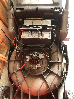
3. The cover should easily lift away from the chassis once the screws are loose. Expect to find a lot of grass clippings and cobwebs on the motor housing and the rest of the chassis that could benefit from some cleaning while you've got the cover off.
4. As mentioned before, a T20 driver will be required to remove the two screws securing the battery bracket. No slots in these screws. Make note of the positive and negative terminals of the old battery so you can make the same connections to the new one.
5. My replacement battery was smaller (not as tall) as the original. I made a shim out of some old cardboard to allow the bracket to be sufficiently tight. Without the shim, the bracket screws were too long. A piece of 1x wood might work as well, but I liked the give in the cardboard to get a snug fit with the bracket.
6. Replace the cover, tighten the screws, and you should be good to go.
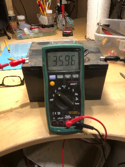
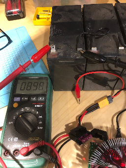
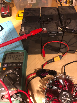
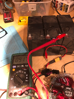
Battery Testing
Initial Values - Charged up to 36v
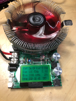
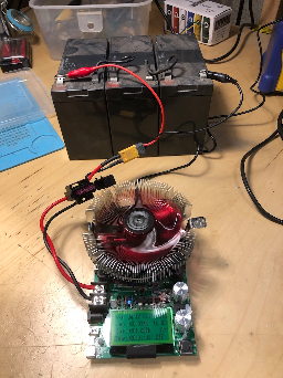
Results
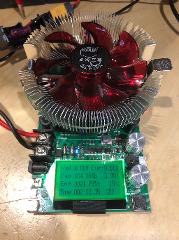
Forgot to set a stop point at 10.8v/battery = 32.4v. Bad John!
When draining down to nothing, I managed to pull 4 Ah from the batteries which is about 40% of the capacity.
Appears, middle battery is not in great shape. Should replace if I find that I can't mow my small lawn with the power I have here. I do have some LiFePo4 batteries I could use to make a replacement if I want more power.
Lithium Battery Replacement
Since I have so many 26650 LiFePO4 batteries, I am going to see if I can build a battery roughly the same size as the 3 lead acid batteries in the mower now.
What We Are Replacing
The battery we are replacing:
| Lead Acid Battery | |
| Width | 149 mm |
| Length | 3*66 = 198 mm |
| Height | 117 mm |
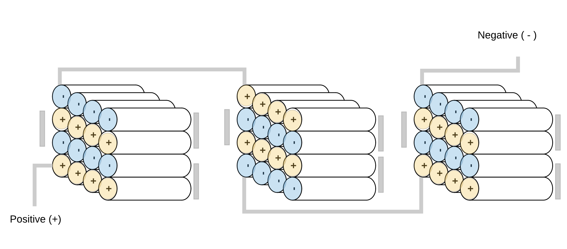
Configuration 12S4P (36 V)
| Number of Cells | 48 |
|---|---|
| Voltage | 36v |
| Ah | 4-6 Ah |
26650 batteries sizeis standardized and it is:
- 26.5 mm (1.04 inches) in diameter, or ~26 mm.
- 65.4 mm (2.57 inches) in length, or ~65 mm.
This configuration would fit the existing battery footprint (slightly smaller) but may grow a bit in size when we add cell spacers and bms.
| Width | 26*4 = 104 mm |
|---|---|
| Length | 65*3 = 195 mm |
| Height | 26*4 = 104 mm |
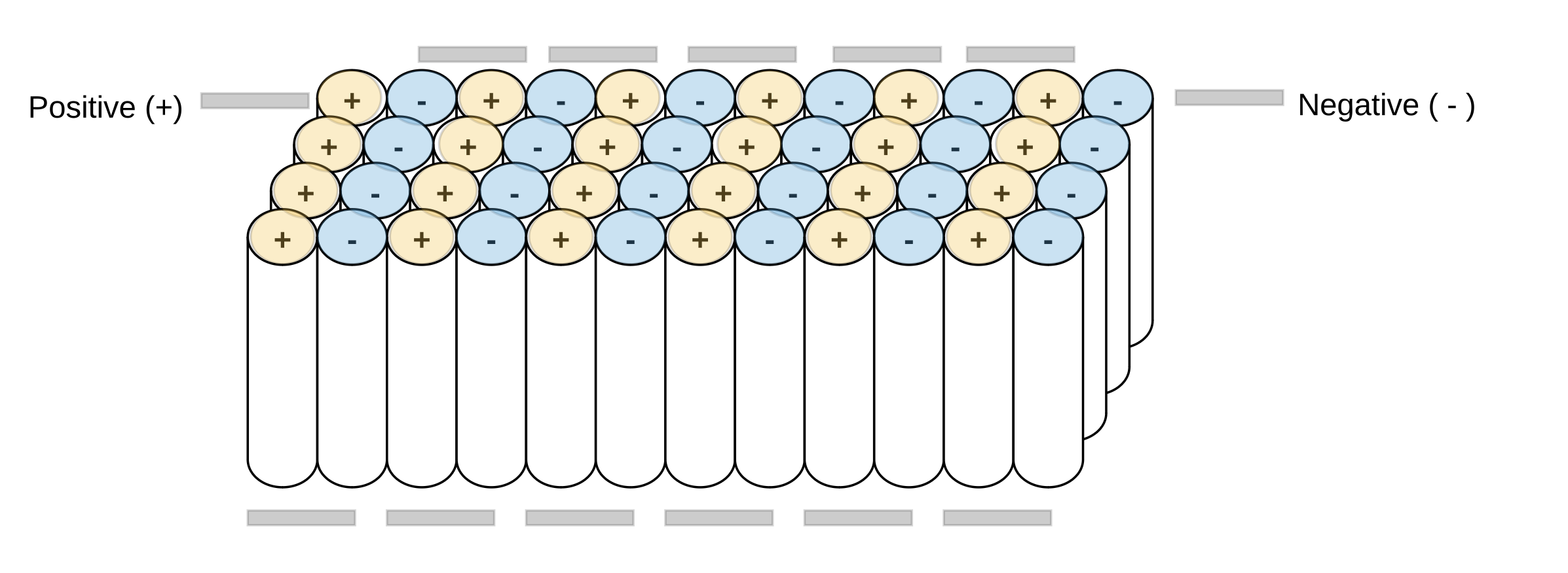
Another Configuration
| Width | 26*4 = 104 mm |
|---|---|
| Length | 26*12 = 312mm |
| Height | 65mm |
Battery Management System
Daier 6S-13S 7S 12S 25A LiFePo4 Life 18650 Battery Cell BMS Charger Protection Board 3.2V
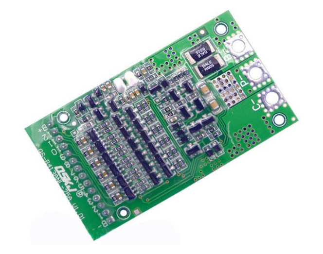
- The polymer lithium li-ion battery protection board, 6S--13S same port/split port all can use
- For different series of batteries, just short the line from B+ to the number of strings you need.
- This protection board adopts mature protection circuit, Taiwan original special IC, 80A high current ultra low internal resistance MOS (single MOS internal resistance as low as 6.5 milliohms), with perfect and stable charging and discharging protection functions
- Small volume and large current can be used in high current applications such as power tools, electric vehicles, and UPS
- The protection board supports both the same port and split port. Support 6S-13S polymer lithium battery (Note: the polymer board can not be used for lithium iron phosphate battery)
The polymer is wired in the same way as lithium iron phosphate, supporting both the same port and split port.
1; B-line to the negative of the lithium battery pack
2; connect the cable (make sure the cable is unplugged from the protection board, start wiring from B-, 8-connect the total negative pole of the battery pack, the second line B1 of the cable is connected to the first string of the positive battery of the lithium battery pack) The third line B2 is connected to the positive pole of the second series of batteries of the lithium battery pack, followed by
3: Insert the cable after checking the error.
4: Take out the C line
5: Whether the total voltage of the lithium battery is equal to the voltage of C-to the positive pole of the battery (the equivalent board is working normally)
Precautions
The B-, C-, and P- lines should be connected with thick wires and ensure that the pads are soldered correctly to the positive and negative terminals of the corresponding device.
Before installing the protection board, the battery must be matched well (the voltage difference between each battery is not higher than 0.05v, the internal temperature difference is not more than 5mΩ, the difference is less than 30mAh), the protection board is to protect each string of batteries, as long as there is a string of batteries If the voltage is too high or too low, it will be protected. The better the battery consistency, the longer the battery life, and the best performance of the protection board.
A single battery needs to be connected in parallel to the required number of battery packs, and then the battery packs are used in series.
When connecting the battery packs in series, please ensure that the voltage of each battery pack is the same. If it is different, please fill each battery pack separately and use it in series. In the discharge test, the circuit with the fastest voltage drop is the differential power.
Parts
| Part# | Image | Description |
|---|---|---|
P360080U 90604959 |
| Charger |
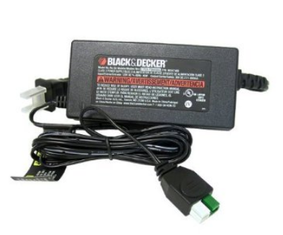
Alterations
Added:
- a voltage meter
- a charging port.
The charging port allows me to charge it with an alternative charger since it appears that my original charger no longer works.
References
| Reference | URL |
|---|---|
| User Manual | |
| Lost Safety Key | https://endless-sphere.com/forums/viewtopic.php?t=42296 |
| Safety Key Info | https://www.lawnmowerforum.com/threads/safety-key.9101/ |
| How to replace battery in MODEL # CM1836 lawn mower | https://www.fixya.com/support/t24859058-replace_battery_in_model_cm1836_lawn |
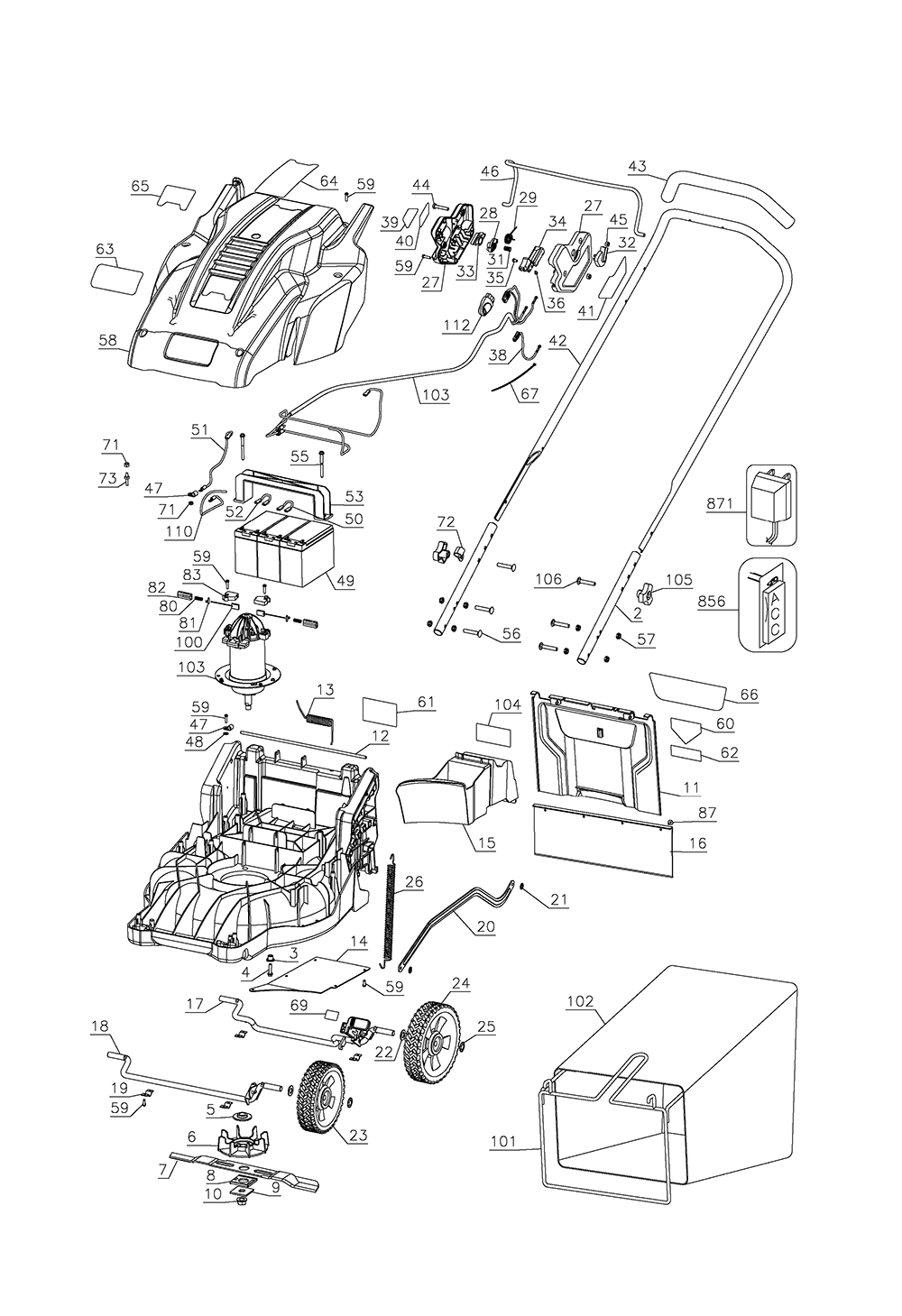
| Parts | https://www.ereplacementparts.com/black-and-decker-cm1836-type-36v-18in-mower-parts-c-4167_9514_173258.html |