Overview
Metal Oxide Semiconductor Field Effect Transistor
"variable resistors controlled by voltage"

How they Work
MOSFETs work like BJT Transistors but trigger based on voltage instead of current.
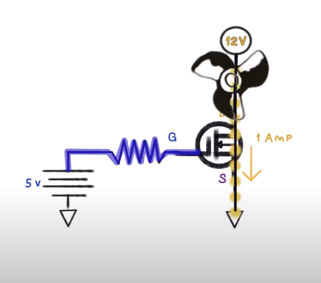
When voltage is applied between Gate and Source, current is allowed to flow between DRAIN and SOURCE.
MOSFETs are variable resistors controlled by voltage. Depending on the voltage applied at the GATE, the resistance between the DRAIN and SOURCE will vary (known as RDSon).
Do I Need a Heat Sink?
Calculate the power you are going to need to dissipate.
Where I is the current your application is going to pull.
Let's assume our little motor will pull 1A and RDS=0.035Omhs I
P=R x I2
=RDS x I2
= 0.035 * 12
= 35 mWatts
The formula to compute the amount of power our MOSFET can dissipate without a heat sink is as follows:
PD = ( (MAX(TJ) - (TA) )/ R0JA
We will need a few more items from the data sheet.
MAX(TJ) - Maximum Junction Temperature
TA - Ambiant Temperature (25C)
R0JA - Thermal Resistance, Junction-to-Ambient, Max
How many watts can we dissipate without a heat sink?
PD = ( (MAX(TJ) - (TA) )/ R0JA
= (175C - 25C )/ 62.5
= 2.4 Watts
NOTE:
The spec sheet will refer to a PD which is higher than our calculation. This is because it assumes that you can keep the MOSFET at 25C while operating which would mean you would need a heatsink.
Testing For Fake Mosfets
https://www.youtube.com/watch?v=XXcEgddzjnI
Testing Procedure
Using a 12V source and a automotive 12v light bulb:
- connect up the bulb and record its current draw from the bulb and the voltage of the supply.
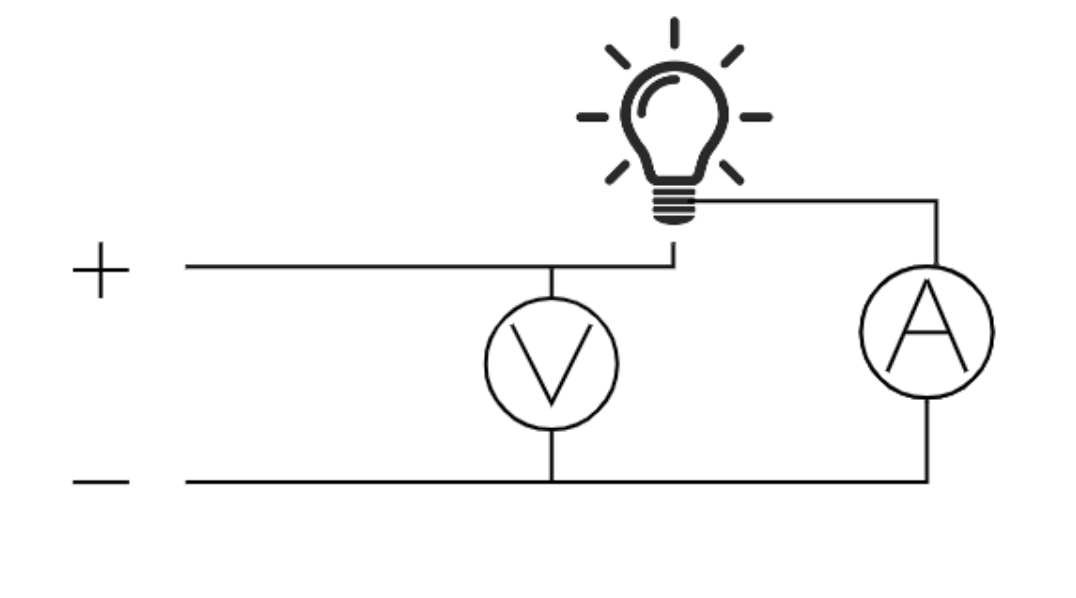
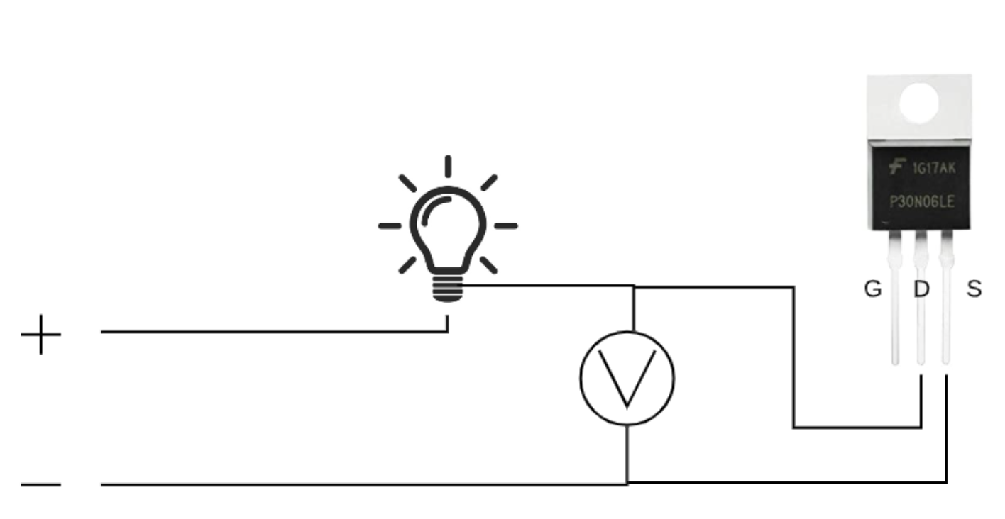
To measure the Voltage from Drain to Source
- connect negative to Source(S)
- connect voltmeter as shown
- connect the + side of the voltmeter to Drain (Bulb should be off)
- connect the + side of the voltmeter to Gate (will activate the mosfet)
- connect the + side of the voltmeter to Drain (Bulb should be ON)
- record voltage
Testing IRFP260
Measurements
Voltage: 12.09v
Current: 2.00A
Voltage Drain to Source: 0.42v
Calculated R(ds)
R(ds) = Vds / I = 0.42v / 2.00A = 0.210 ohms
Datasheet Specs
https://www.vishay.com/docs/91215/91215.pdf
R(ds) = 0.055 ohms
Result
FAKE!
Reference
| Reference | URL |
|---|---|
| MOSFET Transistor | https://www.electronics-tutorials.ws/transistor/tran_6.html |
| MOSFETs Video | https://www.youtube.com/watch?v=GrvvkYTW_0k |
| Real vs Fake MOSFET | How to identify a Fake Transistor? | MOSFET Test | https://www.youtube.com/watch?v=XXcEgddzjnI |