| Table of Contents |
|---|
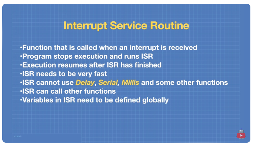
Interrupts
Interrupt Code Sample
Sample Code to to toggle an LED when a button triggers an interrupt.
| Code Block | ||
|---|---|---|
| ||
//Define LED and switch connections
const byte ledPin = 13;
const byte buttonPin = 2;
// Boolean to represent toggle state
volatile bool toggleState = false;
void checkSwitch@) {
//Check status of switch
// Toggle LED if button pressed
if (digitalRead(buttonPin) == LOW) {
// Switch was pressed
// Change state of toggle
toggleState = !toggleState;
// Indicate state on LED
digitalWrite(ledPin, toggleState);
}
}
void setup() {
//Set LED pin as output
pinMode(ledPin, OUTPUT) ;
// Set switch pin as INPUT with pullup
pinMode (buttonPin, INPUT_PULLUP) ;
//Setup Serial Monitor
Serial. begin (9600);
// Attach Interrupt to Interrupt Service Routine
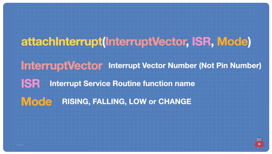
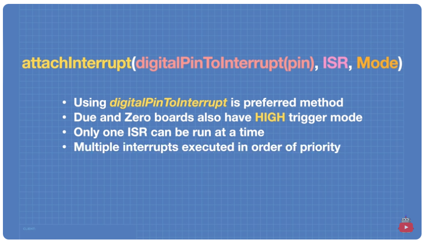
attachInterrupt(digitalPinToInterrupt(buttonPin),checkSwitch, FALLING);
}
void loop() {
// 5-second time delay
Serial.println("Delay Started");
delay (5000);
Serial.println("Delay Finished");
Serial.println(".......
}
|
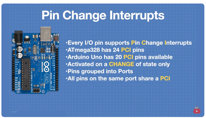
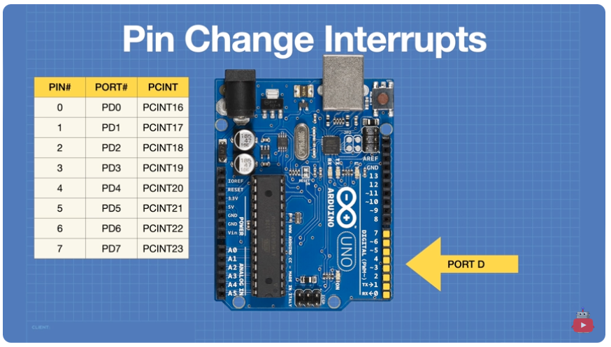
Pin Change Interrupts
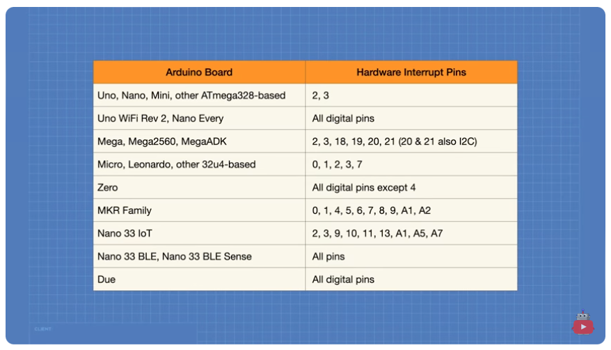
Arduino microcontrollers have a limited number of pins that are hardware interrupt compatible.
To get around this limitation, we can use a pin change interrupts on almost all pins.
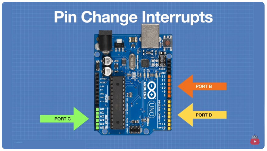
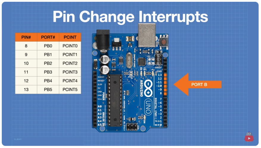
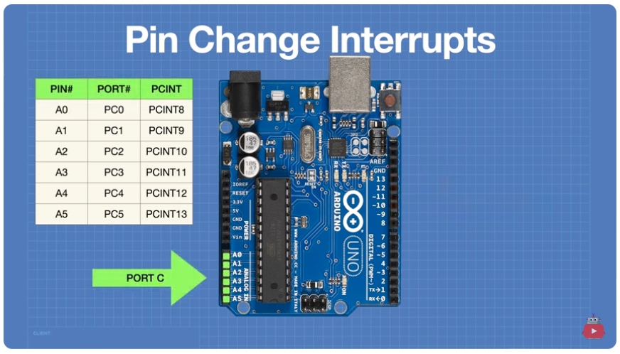
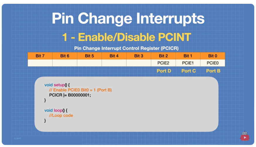
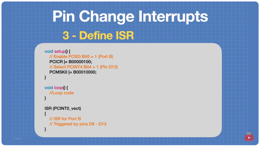
Enable Port B
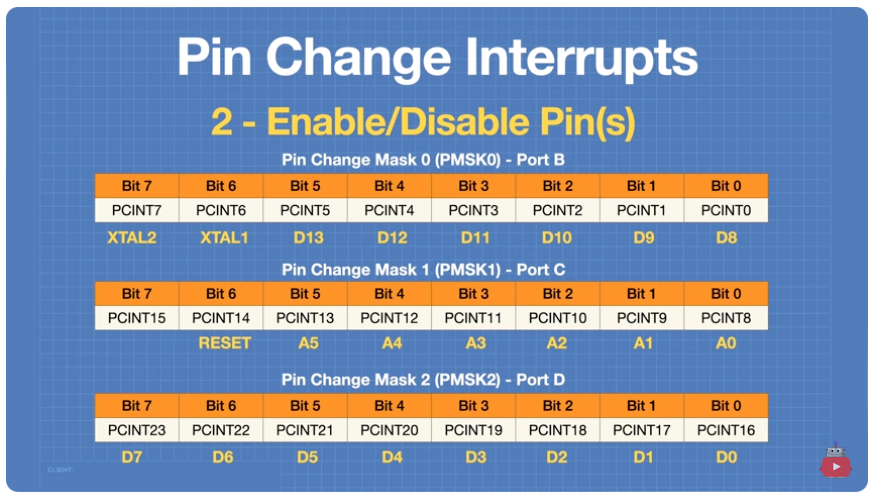
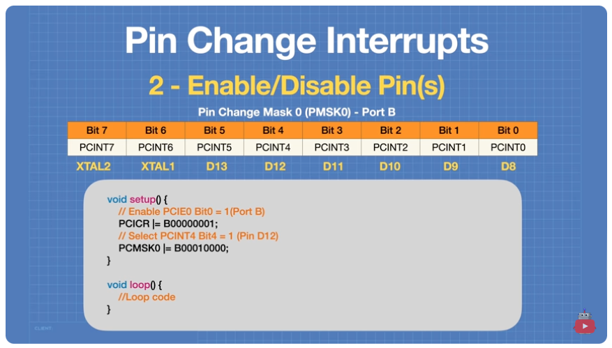
Each port has a mask to enable particular pins.
Activate Pin D12 on Port B
Interrupt Service Routines are pre-defined for each port
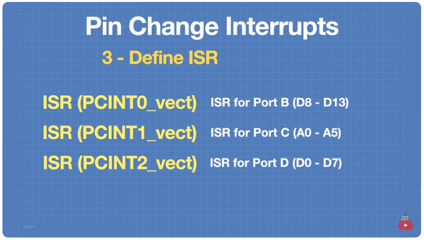
Define the ISR
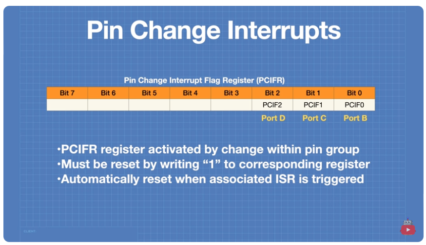
We must rest the interrupt by writing a "1" to the corresponding bit of the PCIFR register. This is not required when using an ISR.
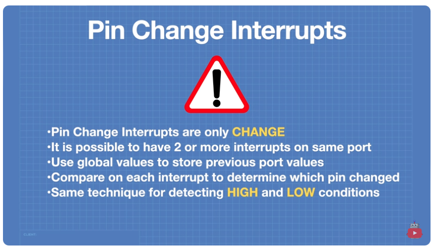
Note about Pin Change Interrupts
Circuit for Example Pin Change Interrupt
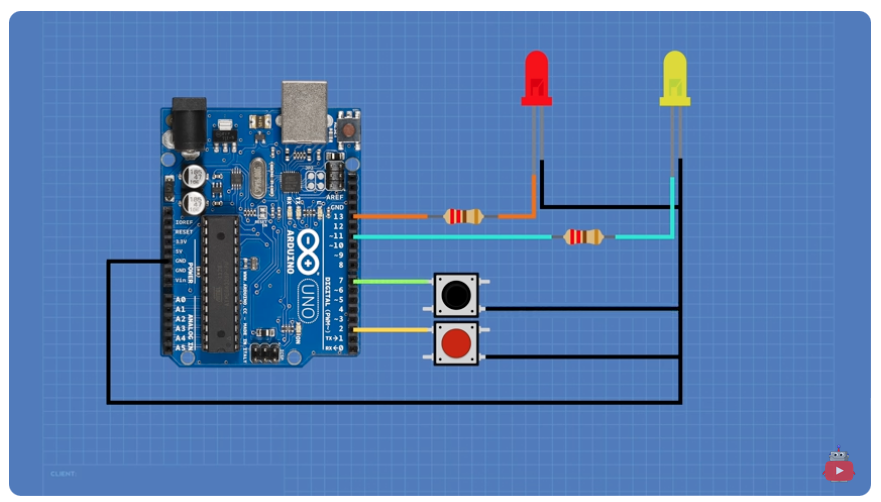
Sample Code
| Code Block | ||
|---|---|---|
| ||
// LEDs and switchs
const byte ledPin1 = 11;
const byte ledPin2 = 13;
const byte buttonPin1= 2;
const byte buttonPin2 = 7;

// Booleans for input states
volatile bool D2_state = LOW;
volatile bool D7_state = LOW;

void setup() {

  // Set LEDs as output
  pinMode(ledPin1, OUTPUT) ;
  pinMode(ledPin2, OUTPUT) ;

  // Set Switches as input with pullup
  pinMode(buttonPin1, INPUT_PULLUP) ;
  pinMode(buttonPin2, INPUT_PULLUP) ;

  // Enable PCIE2 Bit3 = 1 (Port D)|
  PCICR |= 800000100;

  //Enable interrupt on Pin D2 & D7 - Select PCINT18 & PCINT23 (Pin D2 & D7)
  PCMSK2 |= B10000100;
}

void loop(){
 // No code in Loop
}

ISR (PCINT2_vect)
{
  // Port D Interrupt occured

  // Check if this was D2
  if (digitalRead(buttonPin1) == LOW) {

    //Pin D2 triggered the ISR on a Falling pulse
    D2_state = !D2_state;

    //Set LED 1 to state of D2 state boolean
    digitalWrite(ledPin1, D2_state);
  }

  // Check if this was D7
  if (digitalRead(buttonPin2) == LOW) {

    //Pin D7 triggered the ISR on a Falling pulse
    D7_state = !D7_state;
    //Set LED 2 to state of D7_state boolean
    digitalWrite(ledPin2, D7_state);
  }

} |
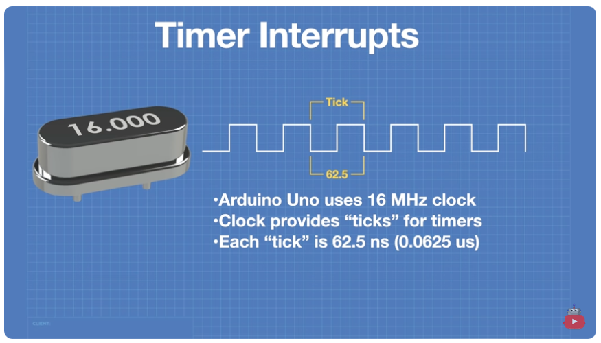
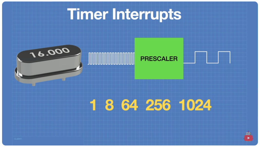
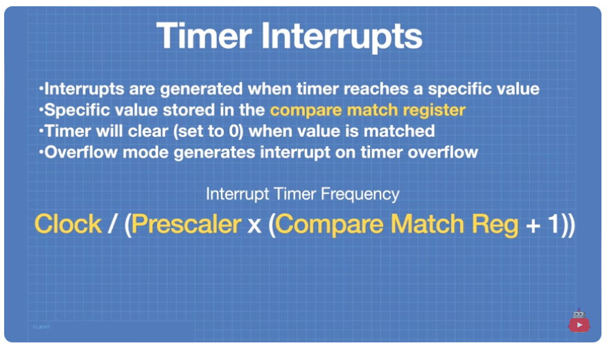
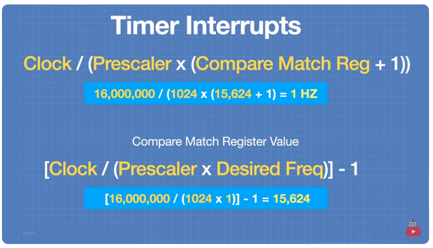
Timer Interrupts
Do not use a timer that is used by another process.
Arduino Uno Timers
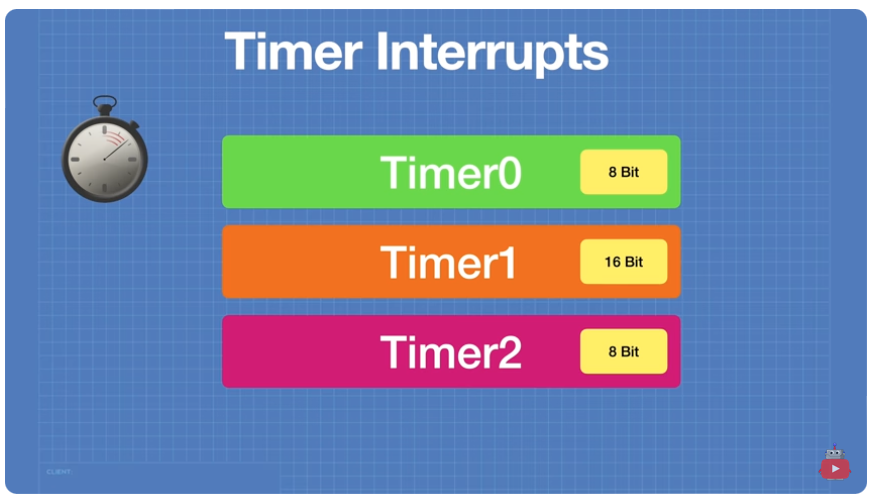
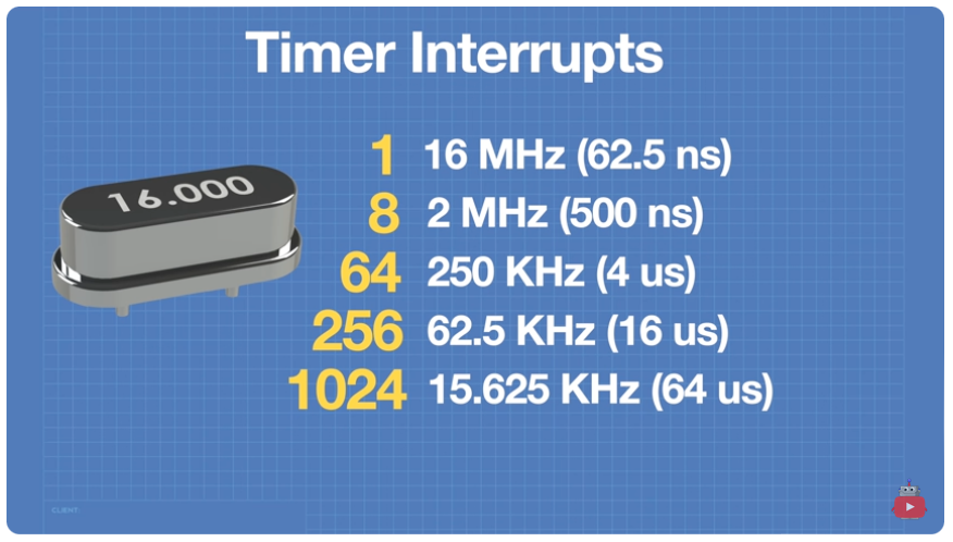
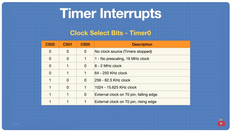
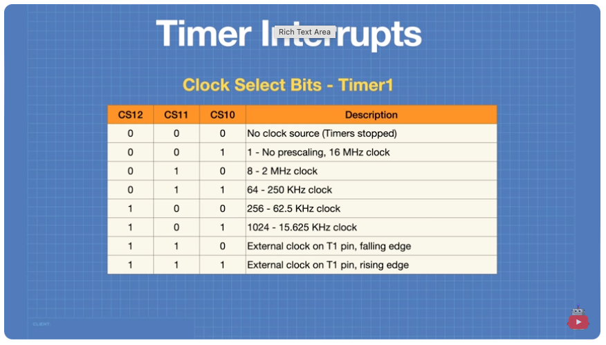
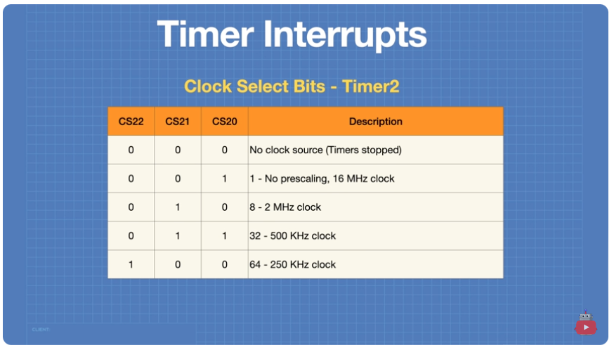
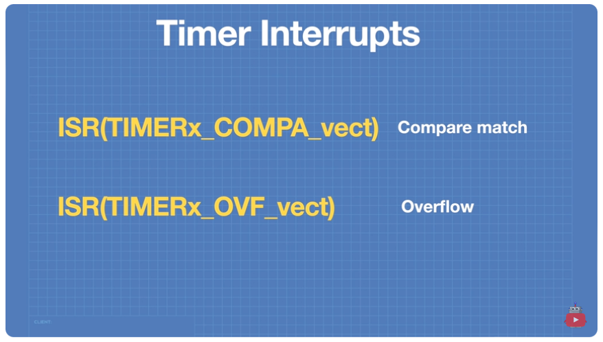
Replace x with 0,1, or 2 representing the timer #.
Code Sample
| Code Block |
|---|
//define the LED pin
#define ledPin 13

//Define timer compare match register value
int timer1_compare_match;

ISR(TIMER1_COMPA_vect){
//Interrupt Service Routine for Compare Mode

  //Preload timer with compare match value
  TCNT1 = timer_compare_match;

  //Write opposite value to LED
  digitalWrite(ledPin, digitalRead(ledPin) ^ 1);
}

void setup(){

  //Set LED as output
  pinMode(ledPin, OUTPUT);

  //Disable all interrupts
  noInterrupts();

  //Initialize Timer1
  TCCR1A = 0;
  TCCR1B = 0;

  //Set timerl_compare_match to the correct compare match register value
  // 256 prescaler & 31246 compare match = 2Hz
  timer_compare_match = 31249;

  //Preload timer with compare match value
  TCNT1 = timer1_compare_match;

  // Preload timer with compare match value
  TCNT1 = timer1_compare_match;

  // Set prescaler to 256 - set CS12 bit in TCCR1B
  TCCR1B = (1 < CS12) ;

  // Enable timer interrupt for compare mode
  TIMSK1 |= (1 < OCIE1A);

  // Enable all interrupts
  interrupts ();

}

void loop() {
  //nothing
} |
Analyzing the Following Code
| Code Block |
|---|
ATmega328P Interrupt Vector Table
- The ATmega328P provides support for 25 different interrupt sources. These interrupts and the separate Reset Vector each have a separate program vector located at the lowest addresses in the Flash program memory space.
...
| Code Block |
|---|
static uint8_t saveTCCR1A, saveTCCR1B; static inline void capture_init(void) { saveTCCR1A = TCCR1A; saveTCCR1B = TCCR1B; //reset TimerCounter 1 TCCR1B = 0; TCCR1A = 0; TCNT1 = 0; TIFR1 = (1<<ICF1) | (1<<TOV1); TIMSK1 = (1<<ICIE1) | (1<<TOIE1); } static inline void capture_start(void) { TCCR1B = (1<<ICNC1) | (1<<ICES1) | (1<<CS10); } static inline uint16_t capture_read(void) { return ICR1; } static inline uint8_t capture_overflow(void) { return TIFR1 & (1<<TOV1); } static inline void capture_overflow_reset(void) { TIFR1 = (1<<TOV1); } static inline void capture_shutdown(void) { TCCR1B = 0; TIMSK1 = 0; TCCR1A = saveTCCR1A; TCCR1B = saveTCCR1B; } #define TIMER_OVERFLOW_VECTOR TIMER1_OVF_vect #define TIMER_CAPTURE_VECTOR TIMER1_CAPT_vect |
References
| Reference | URL |
|---|---|
| Understanding Arduino Interrupts | Hardware, Pin Change & Timer Interrupts | Video: https://www.youtube.com/watch?v=wIcC8-g9Lnw Article with code: https://dronebotworkshop.com/interrupts More articles and tutorials: https://dronebotworkshop.com Join the conversation on the forum: https://forum.dronebotworkshop.com |
| Electronic Basics #30: Microcontroller (Arduino) Timers | https://www.youtube.com/watch?v=IdL0_ZJ7V2s |
| Configuring & Handling ESP32 GPIO Interrupts In Arduino IDE |