Overview
The Sonoff Dual R2 offers control of 2 relays on one board.
Hardware Preperation
This device uses the ESP8285 module which is different than the other SONOFF products.
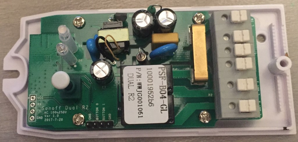
As always, you need to access the serial interface. The four serial pins (VCC, Rx, Tx, GND) are available at the short end of the PCB and can be seen on the left of the image above.
Revising the Tasmota config
Update the user_config.h
Set the SWITCH_MODE to FOLLOW (other options are TOGGLE, FOLLOW, FOLLOW_INV, PUSHBUTTON, PUSHBUTTON_INV, PUSHBUTTONHOLD, PUSHBUTTONHOLD_INV or PUSHBUTTON_TOGGLE ).
// [SwitchMode] TOGGLE, FOLLOW, FOLLOW_INV, PUSHBUTTON, PUSHBUTTON_INV, PUSHBUTTONHOLD, PUSHBUTTONHOLD_INV or PUSHBUTTON_TOGGLE (the wall switch state)
#define SWITCH_MODE FOLLOW
Flashing
Entering Programming Mode
As with all ESP8266/ESP8285 modules pulling GPIO0 to GND is needed to put the chip in programming mode. You need to connect GPIO0 (button 0) and GND during power up.
Luckily both GND and GPIO0 (as BUTTON 0) are available on the second header. A simple jumper between GND and BUTTON 0 while programming will do the trick.
Flashing from the Arduino IDE
- Startup the Arduino IDE
- Open sonoff.ino
- Update parameters in user_config.h. These will be the default values for SSID, etc.
- Set Board Info
Setting the Switch Mode
Reference
| Reference | URL |
|---|---|
| Product Info | http://sonoff.itead.cc/en/products/sonoff/sonoff-dual |
| Sonoff-Tasmota | https://github.com/arendst/Sonoff-Tasmota/wiki/Sonoff-Dual-and-Dual-R2 |
| Sonoff-Tasmota Switch Modes | https://github.com/arendst/Sonoff-Tasmota/wiki/Understanding-SwitchMode-and-SwitchTopic |