
Overview
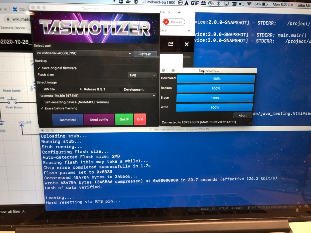
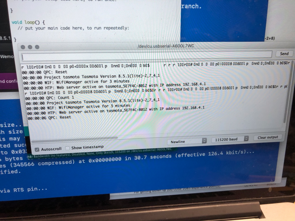
We are hoping to flash Tasmota firmware on our Treatlife DS01C Dimmer switch.
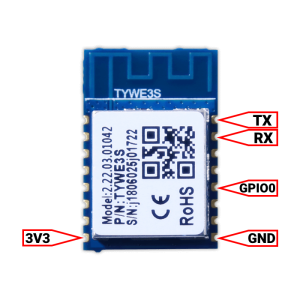
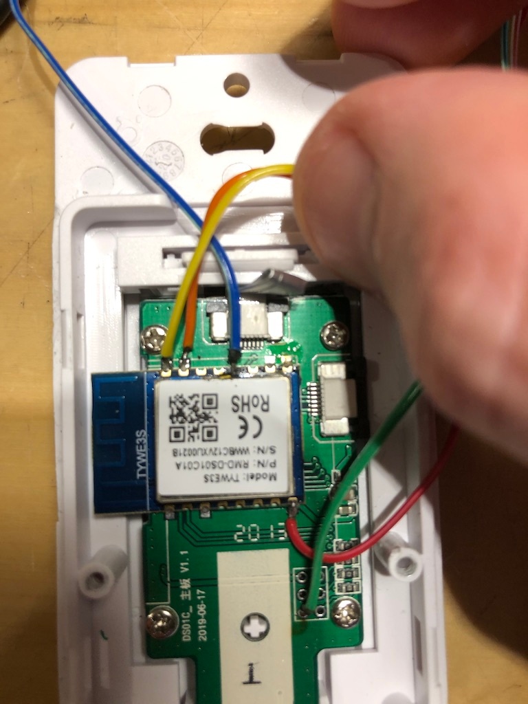
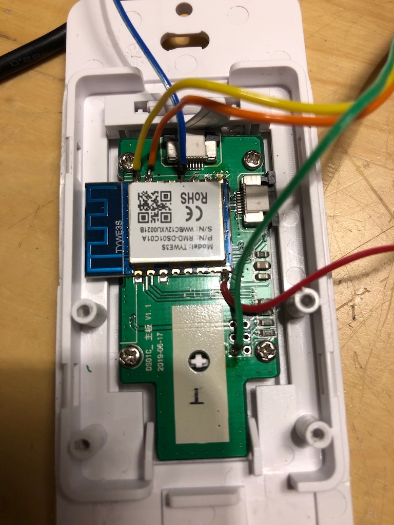
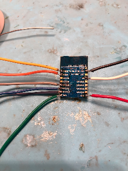
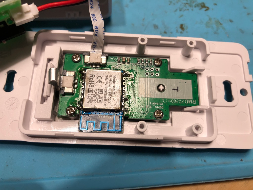
The Treatlife DS01 uses a TYWE3S Chip (ESP8266):
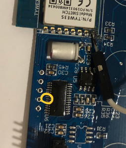
This dimmer has an MCU connected to the TYWE3S over the RX/TX pins.
MCU: BYD - BF7612AM28T W9He
BF7612AMXXE-CN-MCU-Datasheet
Flashing Notes from Net
It seems that some people have had luck flashing by:
- OTA update using TuyaConvert for older versions of this dimmer
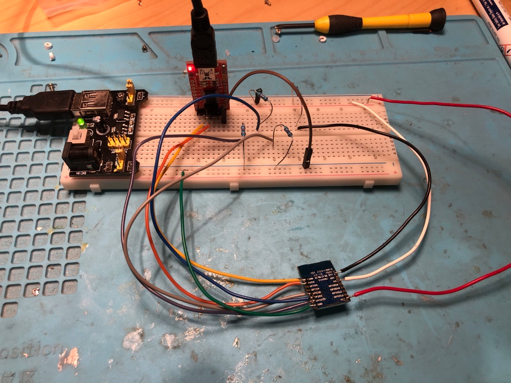
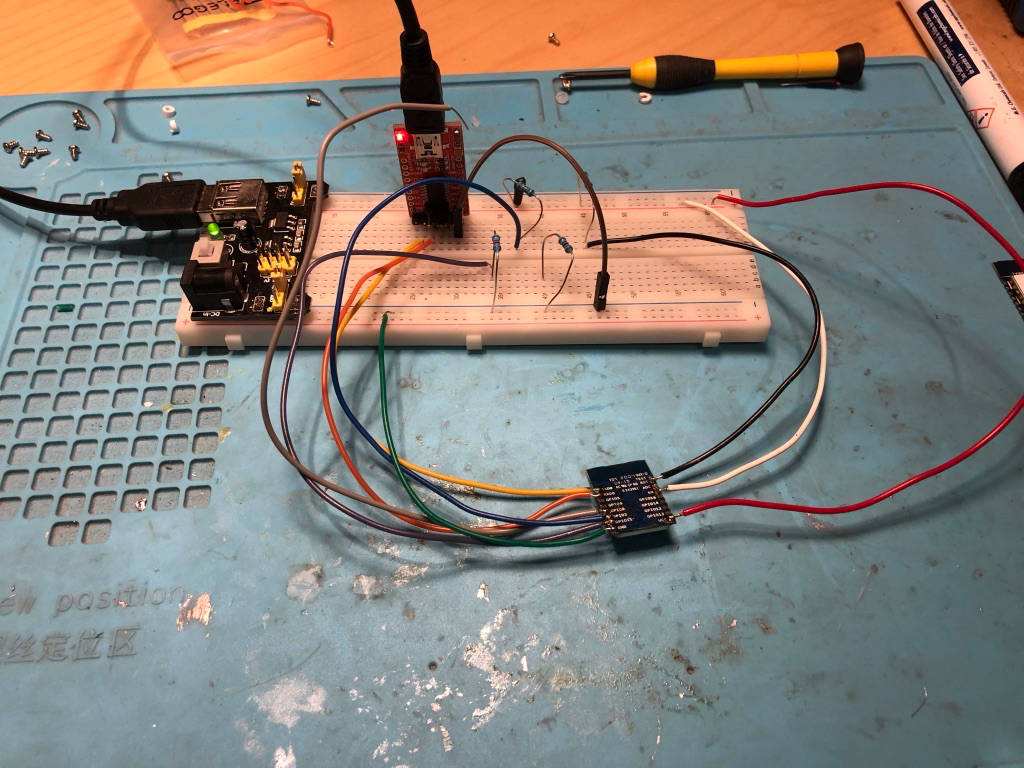
- Flashing using a USB/serial board with the following connections
- Vcc - 3.3V
- TX - RX
- RX - TX
- GND - GND
- GPIO-0 - GND
- Cutting the RX/TX lines on the MCU board and flashing with the above connections.
- Disabling the MCU (disable the chip using it's NRST/RST (Reset) pin if available) and flashing
- Desoldering the TYWE3S board and flashing
Flashing - Disabling the MCU
To boot the TYWE3S in flashing mode, GPIO0 needs to be connected to GND while powering up. It can be left grounded for the entire process. Flashing a TYWE3S connected to a MCU is a bit trickier than one without MCU. This is due the same Rx Tx pins used by MCU and serial programmer for flashing. The TYWE3S cannot be booted to flash mode with MCU sending data over the same pins. To be able to do that, we need to disable MCU from sending data over Rx and Tx pins. There are few ways to do it:
Keep MCU disabled is by identifying the NRST/RST (Reset) pin of the MCU from its datasheet and connect it to GND for the entire flashing process. This will keep MCU disabled while you flash TYWE3S. If there are some contacts or test points in switches that connect to the MCU, you might be lucky to find contacts for RST that you can easily solder onto.
From the above picture, it appears that the MCU differs from the one in the Treatlife DS01C.
Cutting the Rx/TX pin on MCU
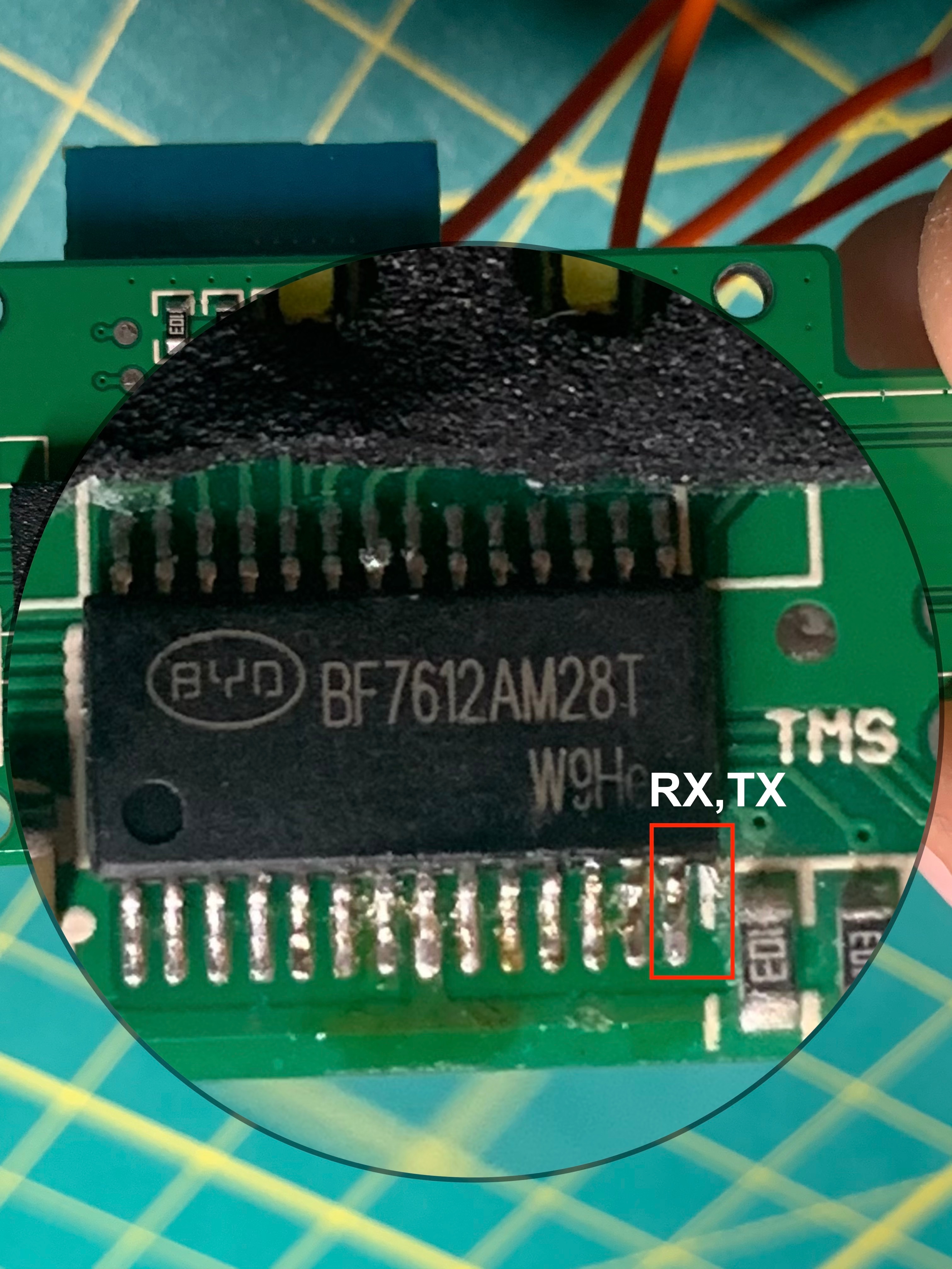
Cutting the RX/TX pins on the MCU was reported to help with flashing the TYWE3S chip without desoldering.
Pictures
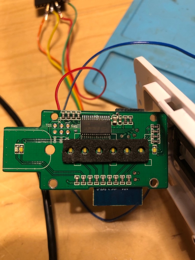
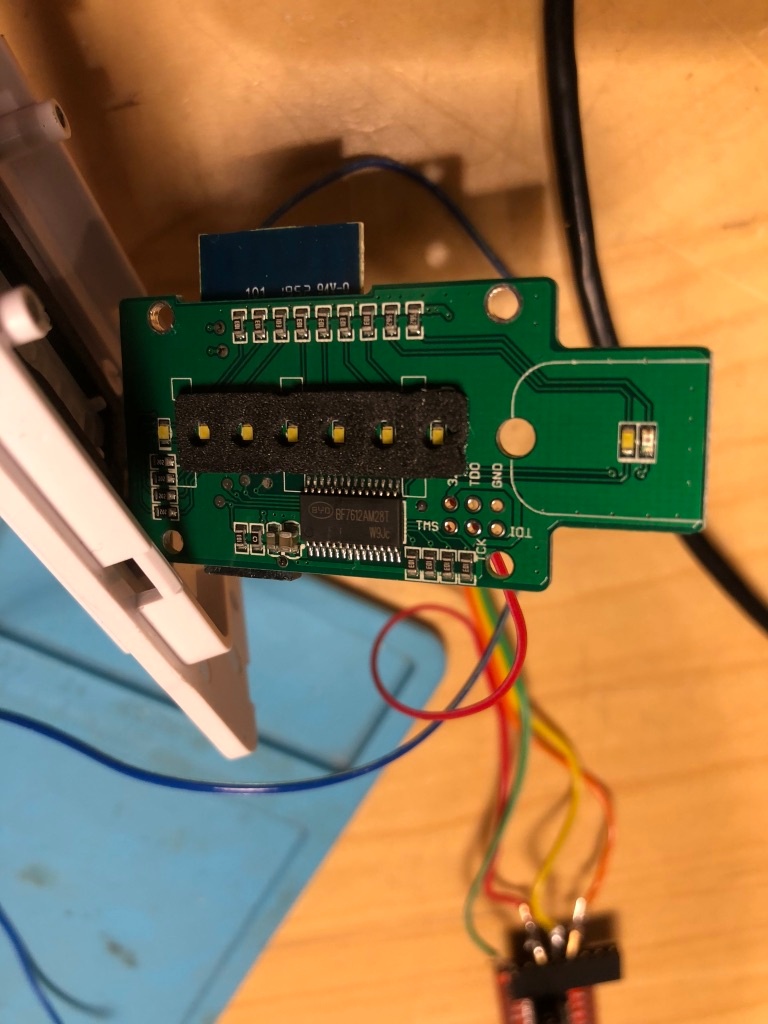
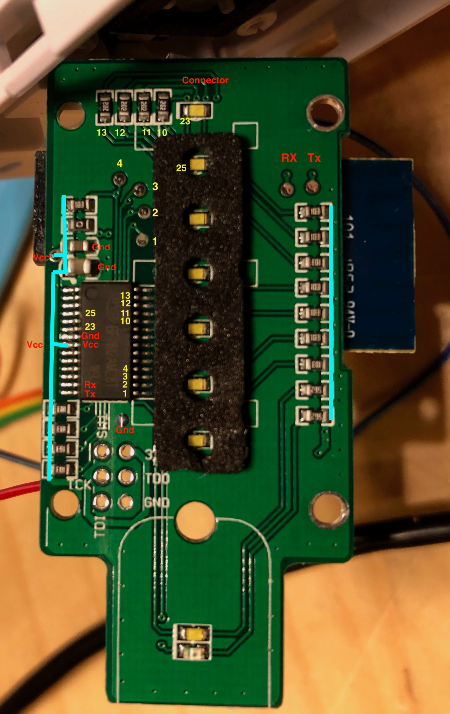
Tracing
Flashing
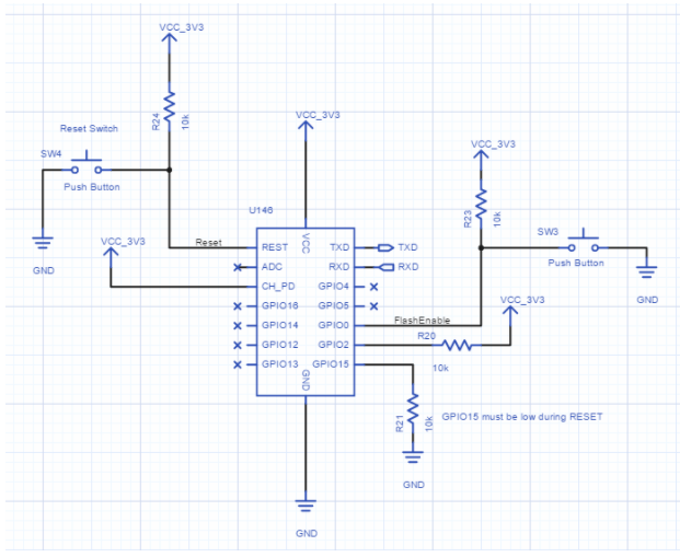
This chip is essentially an ESP8266. The ESP-12 Chip has the same pinout.
We can desolder the TYWE3S board and flash it just like we would an ESP-12.

To flash the ESP-12, you would need to connect it up as follows:
Flash:
Disconnect GPIO-0 and toggle power to configure
Re-assemble
Configuring
https://templates.blakadder.com/treatlife_DS01.html
References
| Reference | URL |
|---|---|
| Tasmota - Tuya MCU Devices | https://tasmota.github.io/docs/TuyaMCU-Devices/ |
| Tasmota - TuyaMCU | https://tasmota.github.io/docs/TuyaMCU/ |
| Tasmota - TuyaMCU Protocol | https://tasmota.github.io/docs/TuyaMCU/#tuya-protocols |
| Tasmota Rules | https://tasmota.github.io/docs/Rules/ |
Trying to flash tasmota on TYWE3S #5377 | https://github.com/arendst/Tasmota/issues/5377 |
| Configuring Tasmota on DS01 | https://templates.blakadder.com/treatlife_DS01.html |