Overview
The objective of this project is to control the Jandy heater using the RS485 interface.
Model: Jandy JXi Gas-Fired Pool and Spa Heater 260N
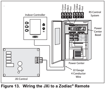
Wiring Connections

Pool/Off/Spa Connector
Connecting to a Remote Pool-Off-Spa Selector (3-Wire Connection) (See b above)
- Turn off the power to both the pool/spa control system and the heater unit.
- Follow service access instructions from Section 6.1.
- Run the wires from the pool/spa control system through the low voltage knockout on the right or left hand side of the heater.
- Connect the wiring from the pool/spa control system to the heater remote control terminal. See Figure 16 item “b”.
- Connect the three wires to the Spa, Pool & Common terminals of the J6 terminal bar.
- Reinstall front panel.
- Restore power to the heater and the pool/spa control system.
NOTE: When a fireman’s switch is being utilized and “hi-lo-com” is selected, the heater will fire automatically when the contacts close even if the user interface on the heater is off.
Configure the Control Panel
- Make sure the pool heater is OFF.
- Press and hold MENU, then the POOL and SPA buttons for 5 seconds to access Service Setup mode.
NOTE: The display will revert back to OFF 1 minute after the last key press.
- Press Up or Down to display REMOTE.
- Press MENU, REMOTE OFF (default) is displayed.
- Use Up or Down to scroll through the Remote options until HI-LO-COM is displayed, then press MENU to select.
- Press POOL or SPA to exit Service Setup mode
RS-4865 Interface
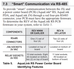
RS485 protocol, wiring & adapters
All pool equipment uses a half duplex RS485 protocol to comunicate between Control Panel, Keypads and inteligent Devices like Salt Water Generators, Variable Speed Pumps, Chemical feeders & some heaters.
There are a few main problems areas that you should have a basic understanding of, that can effect the performance.
RS485 Wiring and Termination (The majority of issues new people have are here)
RS485 USB Adapters and how they actually work in reguard to Pool equiptment. (this becomes very important on busy RS485 bus)
Wiring and Termination
Below is a basic diagram of an RS485 bus
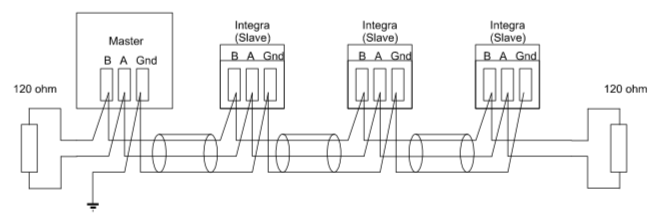
As you can see, each device is connected to 3 wires (Data+, Data- & Ground), and there is a termination resistor at each end of the wiring (or bus).
The ground connection is their so the adapter has a referance point for the voltages in Data+ & Data-, and there is some level of circuit protection.
The termination resistors are their to prodide clear signals and stop reflection. Here is a detailed article on that
References
| Reference | URL |
|---|---|
| Jandy Heater Manuals | https://www.jandy.com/en/products/heaters/jxi Installation: https://www.jandy.com/-/media/zodiac/global/downloads/h/h0574300.pdf Installation Code Handbook: http://www.tagengineering.ca/wp-content/uploads/2015/02/B149-1handbook.pdf |
| Jandy-Aqualink RS485 Protocol | https://github.com/sfeakes/AqualinkD/wiki/Jandy-Aqualink-RS485-protocol |
| AqualinkD - Opensource Software | https://github.com/sfeakes/AqualinkD |
| AqualinkD - Wiki | https://github.com/sfeakes/AqualinkD/wiki |
| Controlling RS485 devices | https://www.troublefreepool.com/threads/controlling-rs485-slave-devices-heater-pump-swg-directly-with-pi.221088/ |