Wiring Connections
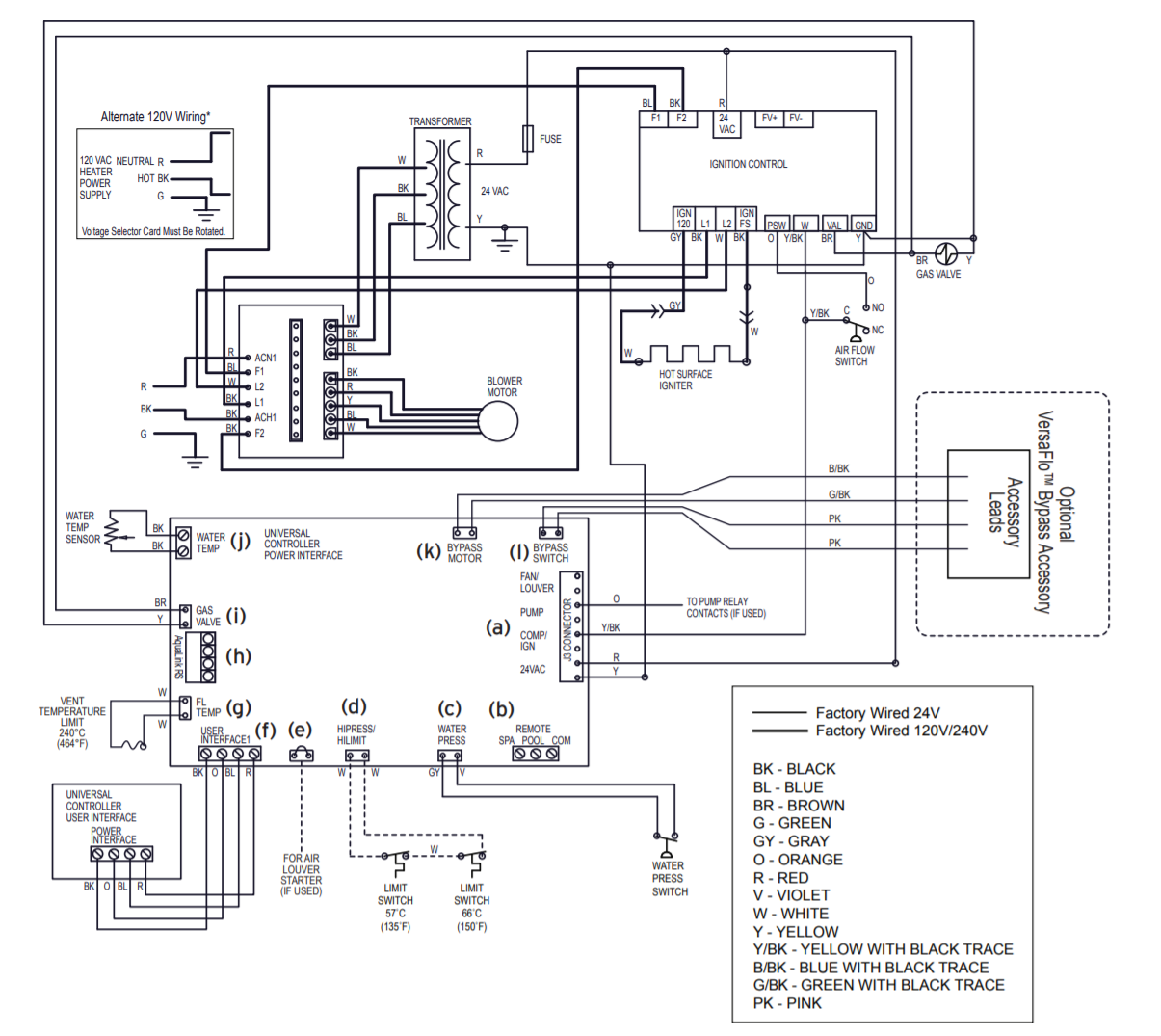
Pool/Off/Spa Connector
Connecting to a Remote Pool-Off-Spa Selector (3-Wire Connection) (See b above)
- Turn off the power to both the pool/spa control system and the heater unit.
- Follow service access instructions from Section 6.1.
- Run the wires from the pool/spa control system through the low voltage knockout on the right or left hand side of the heater.
- Connect the wiring from the pool/spa control system to the heater remote control terminal. See Figure 16 item “b”.
- Connect the three wires to the Spa, Pool & Common terminals of the J6 terminal bar.
- Reinstall front panel.
- Restore power to the heater and the pool/spa control system.
NOTE: When a fireman’s switch is being utilized and “hi-lo-com” is selected, the heater will fire automatically when the contacts close even if the user interface on the heater is off.
Configure the Control Panel
- Make sure the pool heater is OFF.
- Press and hold MENU, then the POOL and SPA buttons for 5 seconds to access Service Setup mode.
NOTE: The display will revert back to OFF 1 minute after the last key press.
- Press Up or Down to display REMOTE.
- Press MENU, REMOTE OFF (default) is displayed.
- Use Up or Down to scroll through the Remote options until HI-LO-COM is displayed, then press MENU to select.
- Press POOL or SPA to exit Service Setup mode
Adding Temperature Probe to Heater
If we want to add a temperature sensor to the heater, we can add one to the outlet (see f in diagram below).
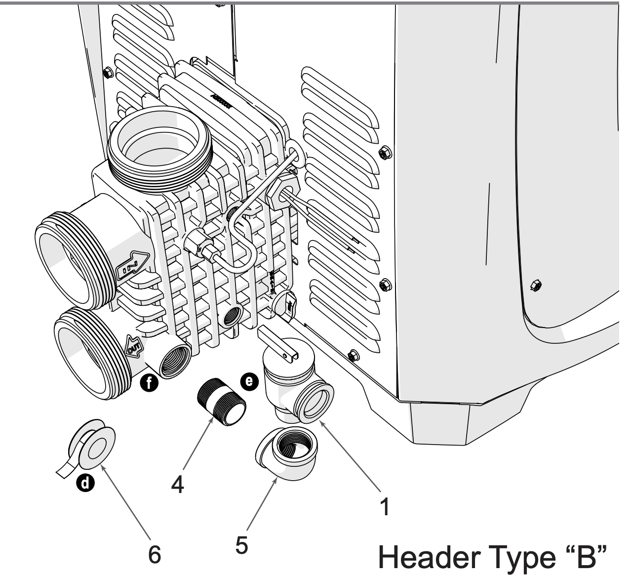
Would add it to "f" - M 3/4" NPT
| No | Part |
|---|---|
| 4 | Brass Nipple 3/4 in |
RS-485 Interface

RS485 protocol, wiring & adapters
All pool equipment uses a half duplex RS485 protocol to comunicate between Control Panel, Keypads and inteligent Devices like Salt Water Generators, Variable Speed Pumps, Chemical feeders & some heaters.
There are a few main problems areas that you should have a basic understanding of, that can effect the performance.
RS485 Wiring and Termination (The majority of issues new people have are here)
RS485 USB Adapters and how they actually work in reguard to Pool equiptment. (this becomes very important on busy RS485 bus)
Wiring and Termination
Below is a basic diagram of an RS485 bus
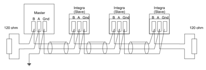
As you can see, each device is connected to 3 wires (Data+, Data- & Ground), and there is a termination resistor at each end of the wiring (or bus).
The ground connection is their so the adapter has a referance point for the voltages in Data+ & Data-, and there is some level of circuit protection.
The termination resistors are their to prodide clear signals and stop reflection. Here is a detailed article on that
Protocol
See:
Table 1 of the manual you posted lists the connections as
Red: +10V
Black: SD+
Yellow: SD-
Green: GND
Serial port runs at 9600 baud, no parity, 1 stop bit, 7-bit chars only.
DTR must be HIGH. RTS must be LOW to receive and HIGH to transmit!
All packets are formatted as follows:
DLE STX <data> <checksum> DLE ETX
Sometimes NULs are sent before and after the packet.
note: if DLE occurs in packet it is escaped as DLE NUL!!!
<data> := <dest><command><args>
<checksum> := the 7-bit sum of bytes DLE, STX and <data>
<dest> := a single byte representing destination for packet
<command> := a single byte with command for destination device
<args> := optional string of bytes for command data
Notes
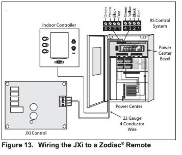
The Jandy LXi/JXi heater needs to be pinged (68 00 00) or sent a command at least every 20 seconds or it shuts off all settings and reverts back to its built in control panel. This means if you had a heat set point on the control panel before you initiated communication it will not resume heating to that temperature without physical interaction. So it's all rs485 or nothing. To turn the heater on in pool mode you send 68 0c e9. That's device 104, command 12, argument 233. (I think there are other command variations in the 0c range but I haven't explored further since i found what i needed). Spa mode is on is 68 0c ee. To continue heating you have to KEEP sending it commands at least every 20 seconds or the heater turns back off. Now that I think about it I'm sure there are 0c commands to turn the heater off without timing out and I'll track them down next. It responds with an 0d 08 if the heater is on or 0d 10 if the heater is off.
So, how do you know when to turn the heater on or off? You have to ping the temperature sensor using the 0x25 block. I've been sending it 68 25 00 but it may not need an argument. It responds with a 7 byte message. 25 33 xx 04 f7 f5 yy. The yy value is the temperature in Farenheit with 20 added for reasons. So 85 degrees would be 105, or 0x69 . 80 degrees = 100 / 64. The xx byte seems to be incrementing slowly except when my heater sat idle, so I presume it is the lifetime hours the heater has been active or maybe amount of gas used. None of the other values change so I have no info on them yet and they may just be filler. Regardless, I don't need any more info to write a controller, I just needed a way to check the current temperature and turn the heat on or off.
To summarize here's the logic loop the power center uses:
1) ping for unit presence about every 10 seconds: 68 00 00
2) get the temperature: 68 25 00
3) if the pool is below whatever the aqualink temperature is set to then also send a heater on command: 68 0c e9
4) ill bet there's a heater off command xx once if temperature is equal or above the set point. 68 0c xx .. or just let it time out.
I'm sure there's extra code to keep the heat from cycling on and off too quickly, and perhaps different heat levels...but this is enough to get started.
I have a Pi Zero that will have a web/api control panel. It will need a hardware stop/start button outside the unit so I can hand over control to the built-in keypad if necessary, plus an air-temp sensor for science.
Phase 2 will be adding my Hayward pump to the slave chain so it will kick up the GPM when the heater is on.
I don't suppose anyone has investigated the control of a Hayward pump?
References
| Reference | URL |
|---|---|
| Jandy Heater Manuals | https://www.jandy.com/en/products/heaters/jxi Installation: https://www.jandy.com/-/media/zodiac/global/downloads/h/h0574300.pdf Installation Code Handbook: http://www.tagengineering.ca/wp-content/uploads/2015/02/B149-1handbook.pdf |
| *** Serial Adaptor Information | |
| Jandy-Aqualink RS485 Protocol | https://github.com/sfeakes/AqualinkD/wiki/Jandy-Aqualink-RS485-protocol |
| AqualinkD - Opensource Software | https://github.com/sfeakes/AqualinkD |
| AqualinkD - Wiki | https://github.com/sfeakes/AqualinkD/wiki |
| Controlling RS485 devices | https://www.troublefreepool.com/threads/controlling-rs485-slave-devices-heater-pump-swg-directly-with-pi.221088/ |