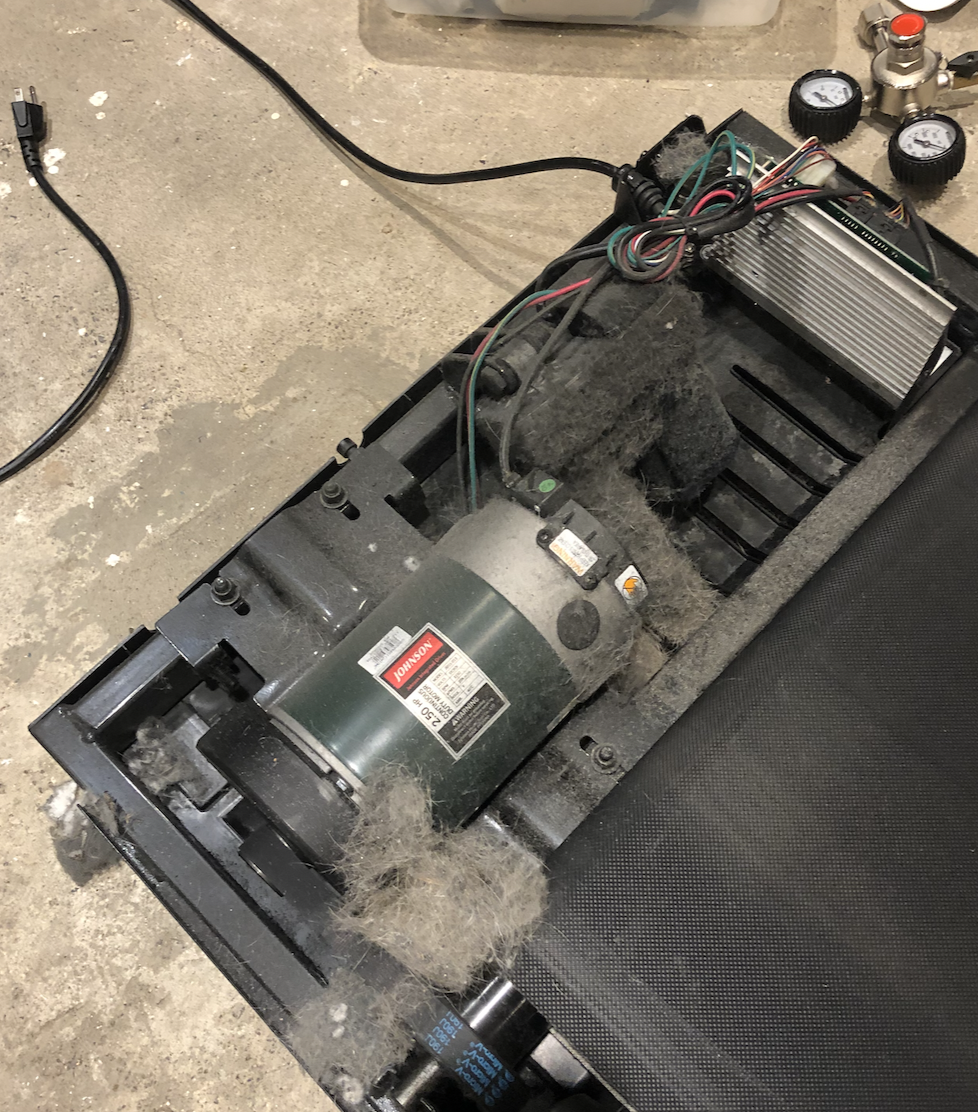
Overview
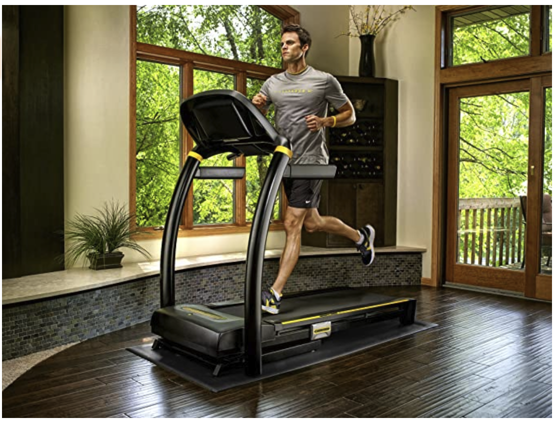
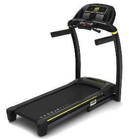
Get the results you want whether you're in training or trying to shed a few pounds with the Livestrong LS8.0T folding treadmill. The LS8.0T is equipped with a 2.5-horsepower continuous-duty motor, powerful enough to deliver speeds of 0.5 to 12 miles per hour and an incline range of 0 to 12 percent (in 0.5-percent increments). As a result, you don't have to compromise when working out--a must when training hard. The treadmill is also extremely comfortable thanks to the MaxComfort cushioning system. The system's adjustable cushioning technology allows you to customize your workout with a softer or firmer feel. With more support for each part of your stride, you'll recover quicker between workouts.
Specifications
- Frame type: Folding
- Drive motor: 2.5 continuous-duty horsepower
- Speed range: 0.5 to 12 mph
- Incline range: 0 to 12 percent (in 0.5 percent increments)
- Running area: 20 by 55 inches
- Cushioning: MaxComfort cushioning system
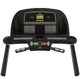
- Display: Backlit LCD and 2 LED feedback windows
- Programs: 9
- Workouts: Manual, Weight Loss 1 and 2, Power Walk 1 and 2, Walk/Run 1 and 2, Incline, and Livestrong.com
- Workout tracking: Livetrack Interactive technology
- Quick speed keys: Yes
- Quick incline keys: Yes
- Heart rate: Contact grips
- Built-in speakers: Yes
- Personal fan: Yes, blower
- Capacity: 325 pounds
- Folded dimensions: 36 by 63 by 44 inches (W x H x D)
- Unfolded dimensions: 36 by 60 by 70 inches (W x H x D)
- Weight: 187 pounds
- Warranties: Lifetime on frame and motor, 2 years on parts, 1 year on labor
About Livestrong Fitness
Manufactured by Johnson Health Tech, Livestrong Fitness equipment is a proud partner of the Lance Armstrong Foundation. Livestrong offers a complete line of home fitness equipment, including treadmills, elliptical trainers, and exercise bikes, as well as Livestrong by Matrix commercial fitness equipment. With Livestrong Fitness, you can find the perfect fitness solution for any budget, goal, or lifestyle.
Pictures
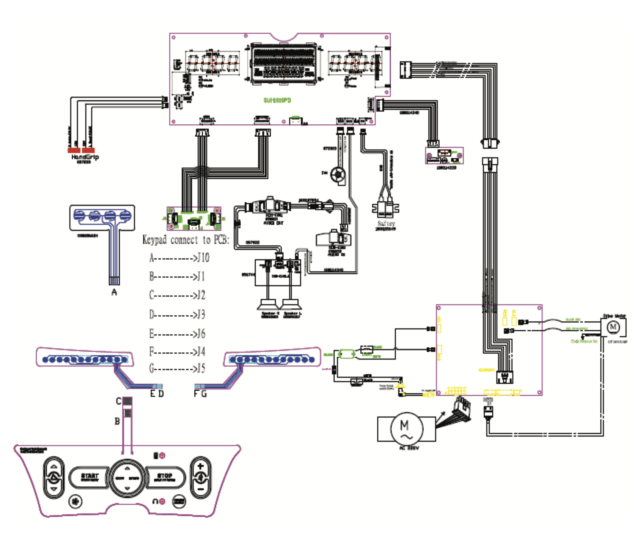
Wiring Diagram

Parts
https://parts.johnsonfitness.com/htm0791-01-ls8-0t-tm641-tm652-canadian-2011
https://fitnessgraveyard.com/collections/livestrong-treadmill-parts
| Part | Description | URL | Compatible Models |
|---|---|---|---|
| 1000111476 | Johnson Fitness 1000111476 Motor Control Board AFG HORIZON | Horizon CT7.1 | |
| 082406 | Speed Sensor & Optical Disk This part contains the optical disc. If the optical disc is not necessary please order 080869 which contains the speed sensor without the optical disc. | See https://parts.johnsonfitness.com/htm0791-01-ls8-0t-tm641-tm652-canadian-2011 | |
| 080869 | Speed Sensor |
Problem
- Short when powered on. Trips breaker.
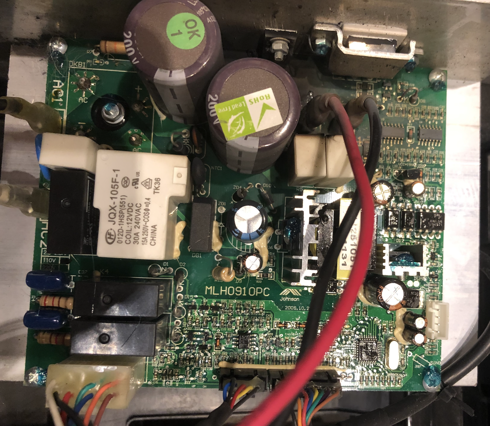
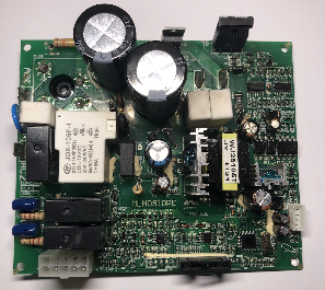
- Problem resides on the motor control board. MLH0910PC Johnson.
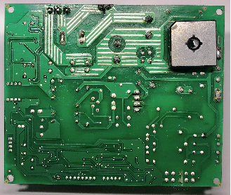
Motor Control Board
Pictures
LED Blink Codes
Blink Codes for Lower Motor Control Board 1000111476
| Number of LED Blinks | Status | Description | Possible Problem Component |
|---|---|---|---|
| 1 | Works normally | Works normally | - |
| 2 | Optical Encoder without feedback | The optical encoder is without feedback for 3 seconds during start procedure or 1 second during workout. | Poor contact or ** Motor not running will trigger this code as well. |
| 3 | Overload | The motor current is over rated tor more than & seconds | Motor |
| 4 | Speed is too large | The motor power components are damaged or speed up too fast. | Motor |
| 5 | The safety key is off | The safety key is off. | Safety Key |
| 6 | The incline motor is stuck or has lost efficiency | There is no signal to the MCB when the incline motor is energized. | Incline Motor |
| 7 | Communication abnormal | No or abnormal communication between the console and MCB. | Console Cable, UCB, or MCB |
| 8 | Bad connection between the incline motor and the MCB | The incline motor cannot go back to absolute "O" degrees. | Incline Motor or MCB |
Workflows
Board Layout

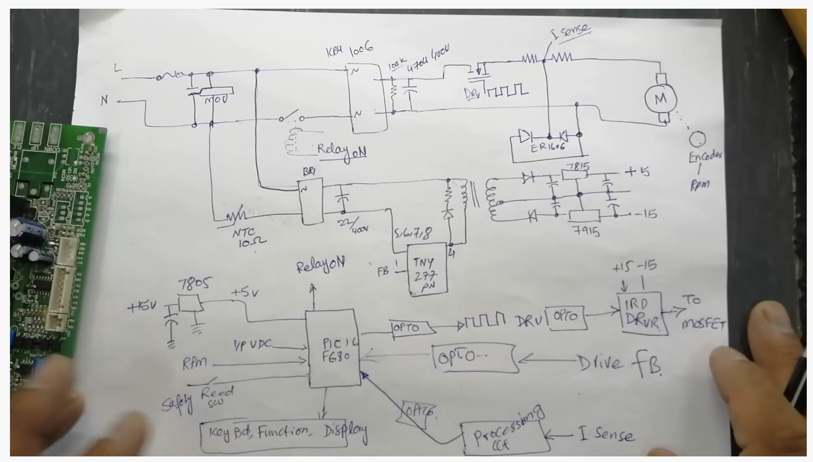
Schematic
Here is a partial schematic created by tracing the board. It is far from complete but could be helpful in the future.


Chips
| Part | Marking | Packaging | Manufacturer | Description | URL | Datasheet |
|---|---|---|---|---|---|---|
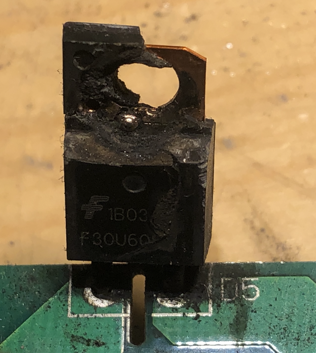
F30U60ST | TO-220F-2 | Fairchild Semiconductor | Power Diode 30Amperes,600Volts Single Insulated Package Ultra Fast Recovery Epitaxial Diode | Alternatives: | ||
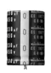
| A132 | A132 | 10 mm between leads | Lelon | Capacitor 680uF, 200v | Alternative: | |
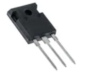
| IRFP260N | MOSFET | IRFP260N | ||||
| Other Chips - Not Replaced | ||||||
| MP3508N | MP3508N | SunB | Bridge Rectifier | MP3508 | ||
| JQX-105F-1 | JQX-105F-1 | Relay Coil: 12 VDC 30A 240VAC | JQX-105F-1 | |||
| SDT-S-112 | Relay 12v 10A 250VAC, 30VDC | datasheet | ||||
| RS207 | SunB | Bridge Rectifier 2A | datasheet | |||
| 5L0380R | Fairchild | Power Switch(FPS) | 5L0380R | |||
LM 339 ST ez82718 | LM 339 | STMicroelectronics | Low-power quad voltage comparators LOC: U3/U4 | LM339 | lm339.pdf | |
| A817 123 | A817 123 | Optocoupler, Phototransistor Output, High Reliability, 5300 VRMS | SFH615AA | datasheet | ||
| 6N136 1049T1 | High Speed Optocoupler, 1 MBd, Photodiode with Transistor Output | 6N136-X009T | ||||
MMBT3904LT1 | 1AM | SOT-23 | Fairchild | NPN Transistor | datasheet | |
| MMBT3906 | 2A | SOT-23 | Fairchild | PNP Transistor | ||


Repair
We identified that the MOSFET (Q3), power diode (D5) and the large capacitors needed replacement on our motor control board. We also had to replace a resistor (R11) which was mark as being 33 ohms but tested at 10K on the board. Ended up replacing this with a 47 ohm through hole resistor.


Replacement Parts
| Part | Specification | Original Part# | Replacement Part# | Image |
|---|---|---|---|---|
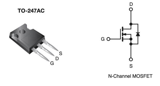
| MOSFET | Power Mosfet | IRFP260N | IRFP260N |
|
| 2x Capacitors | Aluminum Electrolytic Capacitors - Snap In 680uF 200 Volts 20% | LSG681M2D-2540 | LGR2D681MELA40 |
|
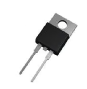
| Power Diode | Forward Current: 30A, Reverse Voltage: 600V Ultra Fast Diode Fully isolated package | F30U60ST | (IDEAL) |
|
RURP3060 with TO-220 insulation Kit (Another Option) |
|


Securing Screws
The board originally had an acetone based lacquer application done to the screws to vibration proof the screws.
Could use nail polish or a thread locker (loctite) as an alternative.
Useful Information
Testing a MOSFET
A simple test to determine if the MOSFET has failed is to check for open circuit between Drain and Source.
Set multi-Meter to Diode Mode
| Positive Lead | Negative Lead | Expectation |
|---|---|---|
| Drain | Source | Open Circuit |
Testing the Treadmill Motor
https://www.youtube.com/watch?v=Ckn5pOMPHHY
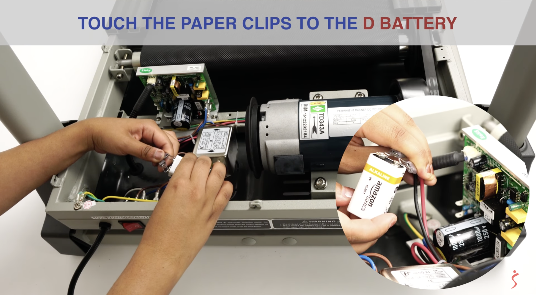
- Disconnect the motor connections from the control board.
- Add paperclips to the connectors to facilitate connecting.
- Connect the paperclips to the battery. (Red to +, black to -) Use fully charge 9V battery or larger (drill battery).
- Motor should start to go.
Reverse Engineered Circuit for another Treadmill
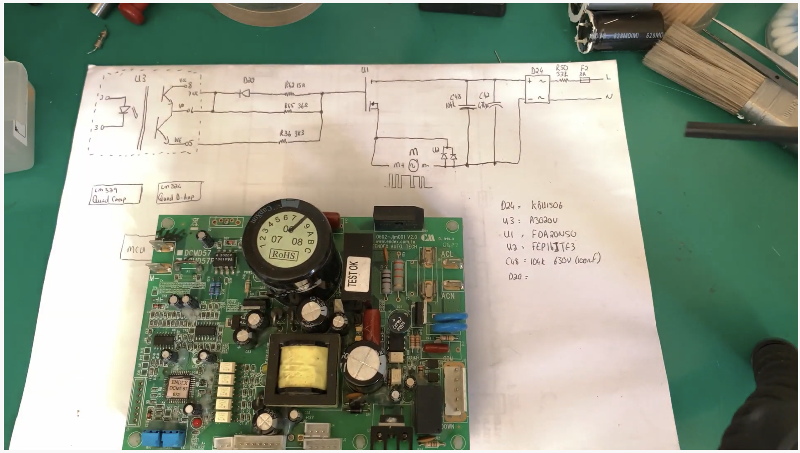
Another:
References
| Reference | URL |
|---|---|
| User Manual | |
Sercice Manual | |
| FoulkesBrau #24 - Lets find the fault on this Trojan treadmill control board DCMD57P PT 1 | https://www.youtube.com/watch?v=gPR6Np6AoN4&t=1s |
| FoulkesBrau #41 - Lets find the fault on this Trojan treadmill control board DCMD57P PT 2 | https://www.youtube.com/watch?v=OrgnpCaxX2s |
| FoulkesBrau #42 - Lets finally repair the fault on this Trojan treadmill control board DCMD57P PT 3 | https://www.youtube.com/watch?v=ErWV33JC440 |
| 271 How to Repair Circuit for TreadMill - Circuit Explained /Troubleshooting | https://www.youtube.com/watch?v=maw1yFxSSjA&t=0s |
| Heatsinking considerations for Common Cathode Rectifying Diode | https://electronics.stackexchange.com/questions/447336/heatsinking-considerations-for-common-cathode-rectifying-diode |
| Electrical Engineering Stack Exchange | https://electronics.stackexchange.com/ |
| Treadmill Motor Speed Controller Circuit | https://www.homemade-circuits.com/treadmill-motor-speed-controller-circuit/ |
| HORIZON FITNESS TREADMILL FAULT DIAGNOSIS | https://electro-medical.blogspot.com/2015/05/horizon-fitness-treadmill-fault.html |