Controller
Schematic
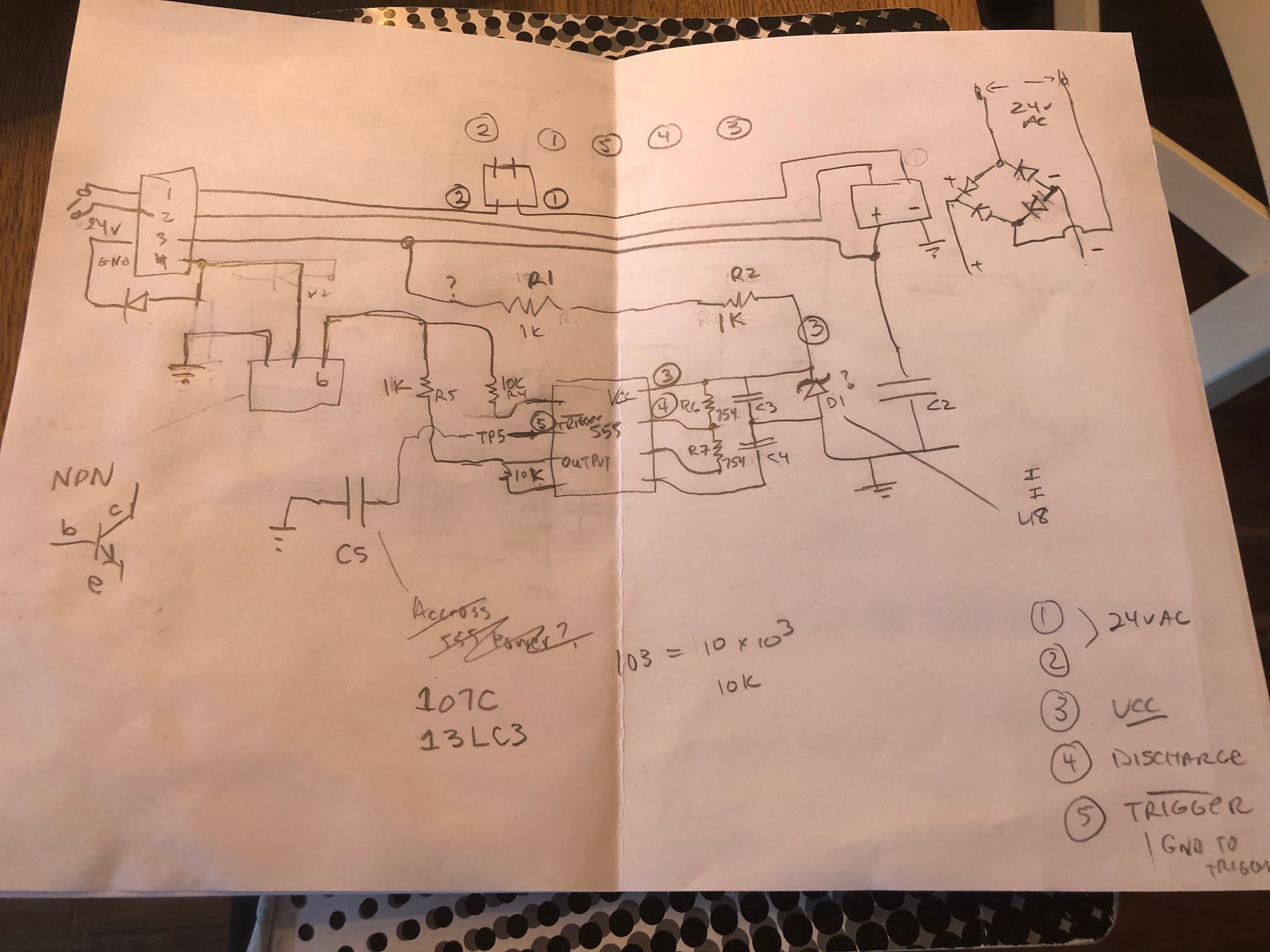
Here is the schematic that I put together based on some testing.
You would think that the GND pin on the 555 would go to ground via a pullup and that would be that.
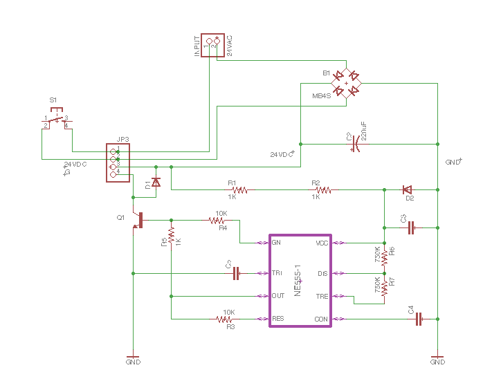
Other thoughts:
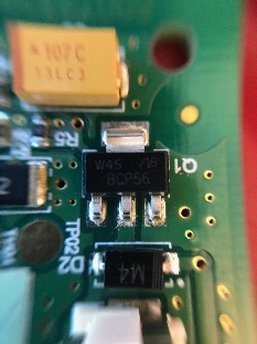
- D2 is a zener diode which acts as a voltage regulator for the 555 chip.
References
| Reference | URL |
|---|---|
| 555 Timer | http://www.ti.com/lit/ds/symlink/lmc555.pdf |