SIN9020S Voltage Meter
Overview
The SIN9020S voltage meter is able to measure:
- voltage
- current
- charge and discharge capacity
- time
- power
Protection Features
- over voltage protection
- under voltage protection
- over current protection
- over-charging capacity protection
Technical Specs
Project | Parameters | ||
Voltage measuring range | Self-powered voltage measurement range | 10V~90V | |
External power measurement range | 0~90V | ||
Current input \ output current measurement range | 0~20A | ||
Display method | Color liquid crystal display | ||
Display Resolution | Voltage | 0.01V | |
Current | 0.01A | ||
Capacity | 0.01AH | ||
Time | 1min | ||
Accuracy | Voltage | 1% + 2 words | |
Current | 2% + 5 words | ||
Measurement rate | 5 times / sec | ||
OFT (out protection) | 0.01H~99.9H | ||
Dimensions (length × width × height) | 79×43×52(mm) | ||
Mounting hole opening (mm) | 76.5*39.2(mm) | ||
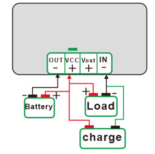
Wiring
From factory, Vext is connected to VCC.
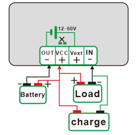
To power the meter from an independent source, you will need to unsolder a jumper inside the meter. Once done, you can power the meter from an independent source.
Useful Functionality
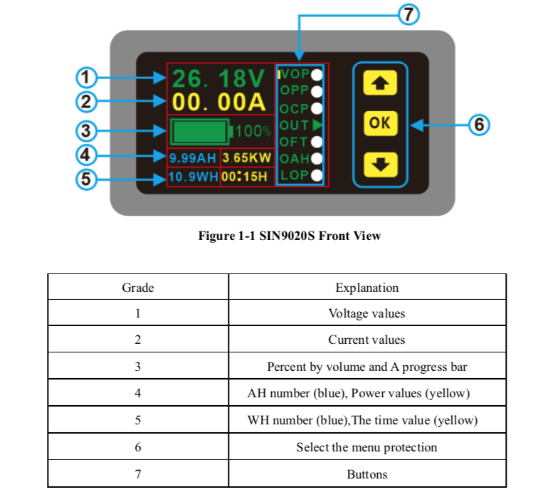
How to Set Functions
If you want to enable a protection function, navigate to it using the up and down arrows and click the OK button. The indicator will turn green when enabled and grey when disabled.
To set the parameters of the protection, press the OK button for three seconds or so. You can then adjust the value by using the arrow keys. Press OK to exit. Factory defaults are 000.
VOP - Over Voltage Protection
OPP - Over Power Protection
OCP - Over Current Protection
OFT - Over Time Protection
OAH - Over Capacity Protection
LOP - Under Voltage Protection
LOP is under voltage protection. When the output voltage drops below the setting, the meter will automatically cut off the output, and the output indicator will change from green to gray.
Does not work with this model since there is no relay
Resetting Meter
To reset the meter, move the arrow below LOP and click OK.
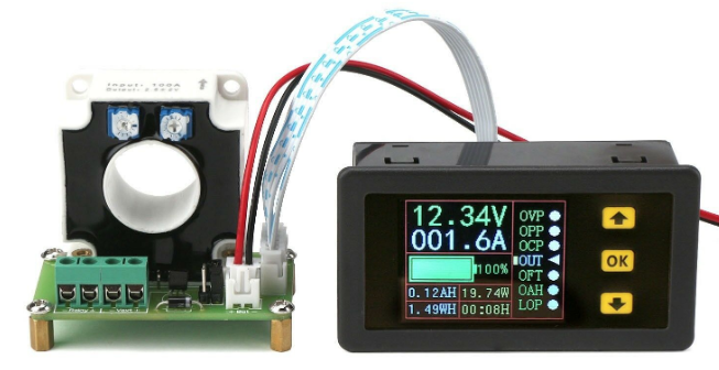
VAC9010H Meter
This model is similar to the SIN9020S meter but has a current transformer for measuring current. This model also has the ability to trigger a relay in the event of low voltage.
Wiring
Connections
All connections to the meter are made from the current capacitor board.
| Connection | Description |
|---|---|
| Bat | Batter Monitoring Connection (10-90v) Meter will get power from this connection when jumper is set to J4. |
| Relay +/- | Relay Connection |
| Vext +/- | Power supply connection. When connecting a relay, this voltage will be used to trigger the relay. (10-60v) |
| Jumper | J3 - Relay or Power Supply Connections J4 - No Relay or Power Supply Connections |
With No Relay or Power Supply Connections
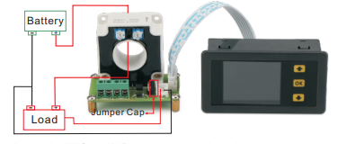
Note: Jumper should be set to J4.
With Independent Meter Power
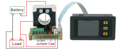
Note: Jumper should be set to J3.
With Relay
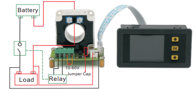
Note: Jumper should be set to J3.
References
| Reference | URL |
|---|---|
| Manual for SIN9020S Meter | |
| Manual for VAC9010H Meter |